You are using an out of date browser. It may not display this or other websites correctly.
You should upgrade or use an alternative browser.
You should upgrade or use an alternative browser.
XAircraft XAircraft X650 tuners of the world, UNITE!
- Thread starter Bartman
- Start date
DucktileMedia
Drone Enthusiast
I did just get new ones, thats why i am so frustrated. There was a miscommunication and they only sent me one set of props.
I would like to thank Jeffrey from www.xaircraftusa.com he has been very helpful and has answered all my "Newbie" questions. My third multi rotor from Jeffrey and xaircraft will be arriving next week. Can't wait.
Thanks Jeffrey - You are a rock star!
Thanks Jeffrey - You are a rock star!
DucktileMedia
Drone Enthusiast
We need more Jeffreys! When does the Octo Jeff come out? ")
Xaircraft USA
Member
We need more Jeffreys! When does the Octo Jeff come out?
Loved your HEXA Frame BTW Yuri, TWO Thumbs up
I am posting this next post for for you and all the custom tuners !!!!
Last edited by a moderator:
Xaircraft USA
Member
MultiMotor Setups using the XAircraft FC1212-S Controller
FC1212-S can be configured to support 4~8 rotors, you can use these rules for motor mixing to make your own multicopter.
Important: DIYer also have to tune the PID parameters(attitude tab in XAircraft Configuration Software) by self.
1 Mixer Rules
2 Example 1: Octa Motor Mixer
3 Example 2: Y6 Motor Mixer
4 Example 3: X8 Motor Mixer
5 Example 4: Hexa +style
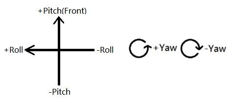
Mixer Rules
First, draw a cross to locate the motors to the areas.
There're only 4 rules to make a mixer settings.
1. All the throttle mixer values should be 100%.
2. The pitch mixer value of +Pitch area motor is +100%, the pitcg of –Pitch area motor is -100%.
3. The roll mixer value of +Roll area motor is +100%, the roll of –Roll area motor is -100%.
4. All clockwise props are in -Yaw ‘area’, all counter clockwise props are in +Yaw ‘area’.
After read the samples, you can try to deduce the mixer for X650 X style or + style for a practice, and check your result according to the X650 settings.
Example 1: Octa Motor Mixer
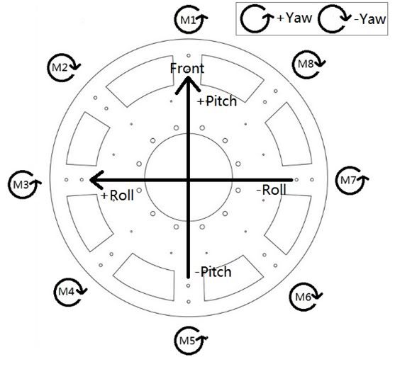
1. All throttles(M1~M8) should be 100%.
2. The pitch of +Pitch area motor is +100%, the pitch of –Pitch area motor is -100%. +Pitch motors are M1, M2 and M8, so the pitch of M1, M2, M8 is 100%. –Pitch motors are M4, M5 and M6, the pitch of them is -100%. But M3 and M7 are not in both +Pitch and –Pitch area, so the pitch of them is 0.
3. The roll of +Roll area motor is +100%, the roll of –Roll area motor is -100%. +Roll motors are M2, M3 and M4, so the roll of them is 100%. –Roll motors are M6, M7 and M8, the roll of them is -100%. M1 and M5 are not in both +Roll and –Roll area, the roll of them is 0.
4. All clockwise props are in -Yaw ‘area’, all counter clockwise props are in +Yaw ‘area’. So M1, M3 and M5 are in +Yaw, their mixer value for yaw is +100%.
The Mixer Result is:
Motor Throttle Pitch Roll Yaw
M1 100 100 0 100
M2 100 100 100 -100
M3 100 0 100 100
M4 100 -100 100 -100
M5 100 -100 0 100
M6 100 -100 -100 -100
M7 100 0 -100 100
M8 100 100 -100 -100
Example 2: Y6 Motor Mixer
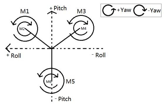
1. All throttles(M1~M6) should be 100% throttle output.
2. The pitch of +Pitch area motor is +100%, the pitch of –Pitch area motor is -100%. In the picture, M1, M2, M3 and M4 are all in +Pitch area, M5 and M6 are in –pitch area.
3. The roll of +Roll area motor is +100%, the roll of –Roll area motor is -100%. In the picture, M1 and M2 are in +Roll area, M3 and M4 are in –Roll area, but M5 and M6 are not in both +Roll and –Roll. So for M5 and M6, the roll mixer value is 0.
4. All clockwise props are in -Yaw ‘area’, all counter clockwise props are in +Yaw ‘area’. So M1, M3 and M5 are in +Yaw, their mixer value for yaw is +100%.
The Mixer Result is:
Motor Throttle Pitch Roll Yaw
M1 100 100 100 100
M2 100 100 100 -100
M3 100 100 -100 100
M4 100 100 -100 -100
M5 100 -100 0 100
M6 100 -100 0 -100
M7 0 0 0 0
M8 0 0 0 0
Example 3: X8 Motor Mixer
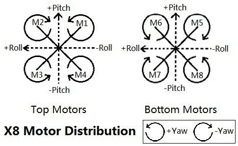
1. All throttles(M1~M8) should be 100% throttle output.
2. The pitch of +Pitch area motor is +100%, the pitch of –Pitch area motor is -100%. In the picture, M1, M2, M5 and M6 are all in +Pitch area, M3, M4, M7 and M8 are in –pitch area.
3. The roll of +Roll area motor is +100%, the roll of –Roll area motor is -100%. In the picture, M2, M3, M6 and M7 are in +Roll area, M1, M4, M5 and M8 are in –Roll area.
4. All clockwise props are in -Yaw ‘area’, all counter clockwise props are in +Yaw ‘area’. So M1, M3, M6 and M8 are in +Yaw, their mixer value for yaw is +100%, othe motors should be -100%.
The Mixer Result is:
Motor Throttle Pitch Roll Yaw
M1 100 100 -100 100
M2 100 100 100 -100
M3 100 -100 100 100
M4 100 -100 -100 -100
M5 100 100 -100 -100
M6 100 100 100 100
M7 100 -100 100 -100
M8 100 -100 -100 100
Example 4: Hexa +style
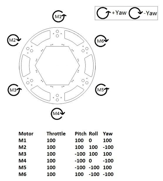
FC1212-S can be configured to support 4~8 rotors, you can use these rules for motor mixing to make your own multicopter.
Important: DIYer also have to tune the PID parameters(attitude tab in XAircraft Configuration Software) by self.
1 Mixer Rules
2 Example 1: Octa Motor Mixer
3 Example 2: Y6 Motor Mixer
4 Example 3: X8 Motor Mixer
5 Example 4: Hexa +style
Mixer Rules
First, draw a cross to locate the motors to the areas.
There're only 4 rules to make a mixer settings.
1. All the throttle mixer values should be 100%.
2. The pitch mixer value of +Pitch area motor is +100%, the pitcg of –Pitch area motor is -100%.
3. The roll mixer value of +Roll area motor is +100%, the roll of –Roll area motor is -100%.
4. All clockwise props are in -Yaw ‘area’, all counter clockwise props are in +Yaw ‘area’.
After read the samples, you can try to deduce the mixer for X650 X style or + style for a practice, and check your result according to the X650 settings.
Example 1: Octa Motor Mixer
1. All throttles(M1~M8) should be 100%.
2. The pitch of +Pitch area motor is +100%, the pitch of –Pitch area motor is -100%. +Pitch motors are M1, M2 and M8, so the pitch of M1, M2, M8 is 100%. –Pitch motors are M4, M5 and M6, the pitch of them is -100%. But M3 and M7 are not in both +Pitch and –Pitch area, so the pitch of them is 0.
3. The roll of +Roll area motor is +100%, the roll of –Roll area motor is -100%. +Roll motors are M2, M3 and M4, so the roll of them is 100%. –Roll motors are M6, M7 and M8, the roll of them is -100%. M1 and M5 are not in both +Roll and –Roll area, the roll of them is 0.
4. All clockwise props are in -Yaw ‘area’, all counter clockwise props are in +Yaw ‘area’. So M1, M3 and M5 are in +Yaw, their mixer value for yaw is +100%.
The Mixer Result is:
Motor Throttle Pitch Roll Yaw
M1 100 100 0 100
M2 100 100 100 -100
M3 100 0 100 100
M4 100 -100 100 -100
M5 100 -100 0 100
M6 100 -100 -100 -100
M7 100 0 -100 100
M8 100 100 -100 -100
Example 2: Y6 Motor Mixer
1. All throttles(M1~M6) should be 100% throttle output.
2. The pitch of +Pitch area motor is +100%, the pitch of –Pitch area motor is -100%. In the picture, M1, M2, M3 and M4 are all in +Pitch area, M5 and M6 are in –pitch area.
3. The roll of +Roll area motor is +100%, the roll of –Roll area motor is -100%. In the picture, M1 and M2 are in +Roll area, M3 and M4 are in –Roll area, but M5 and M6 are not in both +Roll and –Roll. So for M5 and M6, the roll mixer value is 0.
4. All clockwise props are in -Yaw ‘area’, all counter clockwise props are in +Yaw ‘area’. So M1, M3 and M5 are in +Yaw, their mixer value for yaw is +100%.
The Mixer Result is:
Motor Throttle Pitch Roll Yaw
M1 100 100 100 100
M2 100 100 100 -100
M3 100 100 -100 100
M4 100 100 -100 -100
M5 100 -100 0 100
M6 100 -100 0 -100
M7 0 0 0 0
M8 0 0 0 0
Example 3: X8 Motor Mixer
1. All throttles(M1~M8) should be 100% throttle output.
2. The pitch of +Pitch area motor is +100%, the pitch of –Pitch area motor is -100%. In the picture, M1, M2, M5 and M6 are all in +Pitch area, M3, M4, M7 and M8 are in –pitch area.
3. The roll of +Roll area motor is +100%, the roll of –Roll area motor is -100%. In the picture, M2, M3, M6 and M7 are in +Roll area, M1, M4, M5 and M8 are in –Roll area.
4. All clockwise props are in -Yaw ‘area’, all counter clockwise props are in +Yaw ‘area’. So M1, M3, M6 and M8 are in +Yaw, their mixer value for yaw is +100%, othe motors should be -100%.
The Mixer Result is:
Motor Throttle Pitch Roll Yaw
M1 100 100 -100 100
M2 100 100 100 -100
M3 100 -100 100 100
M4 100 -100 -100 -100
M5 100 100 -100 -100
M6 100 100 100 100
M7 100 -100 100 -100
M8 100 -100 -100 100
Example 4: Hexa +style
Last edited by a moderator:
Xaircraft USA
Member
Alittle video from the X650V-8 with a hard mounted GoPro !!! ENJOY .... I hope LOL !!!
Last edited by a moderator:
Nice video Jeffery, You were right this x450 pro flys like a dream. I was amazed at how fast you can drop and it stays level! This thing is gona be awesome with the fat shark goggles and the gopro. Finally a high quality quad that flys great, easy to build and parts are priced right. I didnt even have to build anything to mount my equipment on. Thanks for all the help, its hard to find a store these days where you can call and get help. I ordered some spare parts, your prices are awesome!
Xaircraft USA
Member
Nice video Jeffery, You were right this x450 pro flys like a dream. I was amazed at how fast you can drop and it stays level! This thing is gona be awesome with the fat shark goggles and the gopro. Finally a high quality quad that flys great, easy to build and parts are priced right. I didnt even have to build anything to mount my equipment on. Thanks for all the help, its hard to find a store these days where you can call and get help. I ordered some spare parts, your prices are awesome!
WOW, We do our best to Serve !! Glad you like the X450, Quadflyer!! Can't say thanks enough for that brilliant recommendation, THANK YOU, THANKYOU
Xaircraft USA
Member
Been testing GPS-S ... Doing wonderful Will post VIDEO !! Forgot to film !
Will post VIDEO !! Forgot to film !Is my x650 shipping to me this week?
+1, any news?
Been testing GPS-S ... Doing wonderful
I saw a video of position hold and return to home, awesome! That is gona be great when flying fpv like I do. It could save a crash in case of video downlink loss. Cant wait to see your video! Hey I can sell the gaui and buy the gps for my x450 pro lol
DucktileMedia
Drone Enthusiast
By as many extra props as you can get your hands on as you can only use Xaircraft props and if they break there arent many online stores that sell them. Also, I had a motor lock up on me this weekend so it might not be a bad thing to have an extra motor on hand as well.
Xaircraft USA
Member
By as many extra props as you can get your hands on as you can only use Xaircraft props and if they break there arent many online stores that sell them. Also, I had a motor lock up on me this weekend so it might not be a bad thing to have an extra motor on hand as well.
Props will be readily available in a FEW days. GPS-S and Compass systems are working flawlessly. Flying 5 to 6 minutes just watching it set there, the "heading hold" on the Compass works flawlessly, "Return to home" is also working fantastic, will be posting plenty of video. Ordering ALL I can. Everyones orders will be shipping soon. For the first time since the V series hit the market we will have standing inventory on all kits and 99% of All available XAircraft Parts ... Unless there is a MAD rush on them, which wouldn't surprise me after these videos start posting... Want to say, "Thanks to everyone for their patience". Have been covered up with builds that needed to see their NEW homes. Trying to catch up today and tomorrow and will be available to answer Emails, phone calls ETC. Had to turn off the ringer for 2 or 3 days ... 2 many builds and too many calls... ALmost caught up..
Last edited by a moderator:
Xaircraft USA
Member
hi Jeffery
I purchased a x650 v8 from cncheli, will you be able to help me properly configure it, and what spare parts do you recommend I have on hand? I wish I had know about xaircraft USA before I placed my odder with CnC
steven
Will do my very best to help everyone who has XAircraft Questions, We service XAircraft, Not just XAircraft USA Customers. THANKS Again to everyone for their patience !!!!
Xaircraft USA
Member
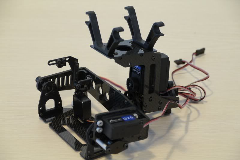
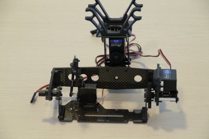
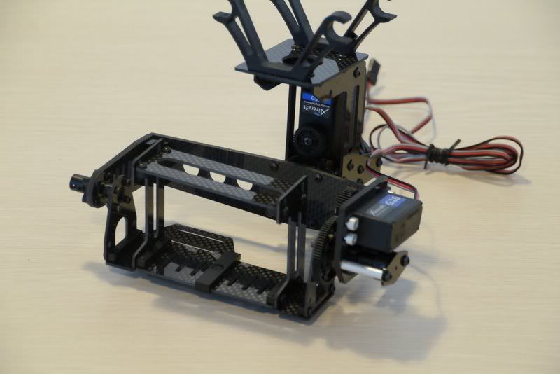
Posting NEW Pictures of the XAircraft Camera Mounts !! Jingchen just sent me pictures. They are finishing manuals for them SOON !!!
Last edited by a moderator:
Xaircraft USA
Member
Posting NEW Pictures of the XAircraft Camera Mounts !! Jingchen just sent me pictures. They are finishing manuals for them SOON !!!
Last edited by a moderator: