New Camera Mount Design Advice Please

Borneoben

Member
Hi Guys

I have been working on a new design for a Camera / Photography Rig and I would like to get some feedback from you all. Please feel free to jump in and let me know what you think. I would hate to be heading in the wrong direction!
I decided to approach the design from a slightly different angle. I wanted something that can be assembled easily with cheap materials. (Laser cutting is required but this can be done surprisingly cheaply) I have chosen 1/8 (3.75mm) Light Ply as its light and strong and I believe it to be suitable for the job.
Im sure most people would like to see Carbon or G10 but one big draw back of these materials is you normaly have to use fasteners and spacers which add weight. The nice thing about the 1/8 lite ply is that you fix it all together then use thin CA to wick into all teh joints. So the over all structure is light and strong. Admittedly it makes it a little more dificul to repair. It can be done but is a more involved than un bolting a broken part and bolting on a new one. However I hope to have the parts at such good prices you could just replace whole assemblies an not bother to repair.

I realised that most of the AP ships around seem to have a camera gimbal that is designed to fit onto an existing airframe.
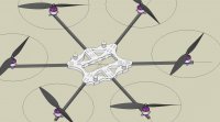
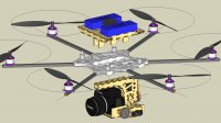
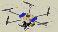
I decided to design my airframe around the camera gimbal but also make it so the camera gimbal can be mounted on another airframe easily. The Airframe is a simple frame that can be swapped out for a different configuration. If you start out with a Quad but want to upgrade to a Hexa its a simple process and should be fairly quick and easy. My first frame will be a Flat Hexa but anything can be done. I may decide to bolt the motors through the Arms or use a simple motor mount that is cheap and readily available from BlueSkyRC such as This one and This one. Basically any common motor arm combination can be achieved.

So
Camera gimbal first
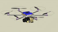
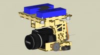
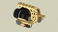
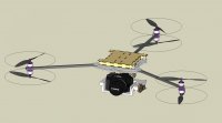
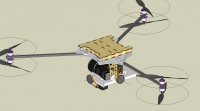
I decided to follow the VerticalView camera mount general layout but address some of its issues.
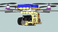
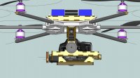
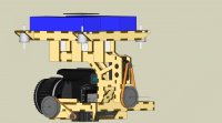
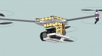
The main camera platform roll axis is held in place by 4 ball races to remove any flexing
The pivot shaft is intended to be a cut down main shaft from a 450 size heli so will be 6mm Diameter and made from hardened steel. Should be easy to cut with a Dremel cut off wheel and if your clever and cut it in the right spot, you should not need to drill it which could be difficult.
The Camera platform pitch axis is also held in place by 4 bearings 2 on each side. Also to be cut down 450 size Heli Main shaft. To be able to use the part of the main shaft that already has the holes drilled you may need to cut down 3 main shafts. However 450 size clone heli parts are super cheap!
All Bearing on the camera gimbal will be the same Flange type and all the same dimensions for easy maintenance and parts supply. (I have yet to finally specify the bearings)
I also believe that the best method to move the gimbal is via belt drive. Please can you guys recommend a drive ratio? What is the drive ratio on the Vertical View mount? Once I know the most common drive ratio I will be able to source the Belts and Pulleys.

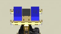
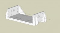
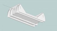
The Gimbal rigidly mounts to the main Radio equipment platform but can also be easily removed.
The Main platform is also designed to mount the FC and the Main Battery Packs. Its this platform that is mounted ontop of the main Airframe via Gelmec Isolation Dampers. The actual spec of these dampers is yet to be finalised and will be determined by talking to the Gelmec engineers and experimentation. Servos I intend to use are Hyperion Atlas DS20FMD as thats what I have in tehspres box! Specs are HP-DS20-FMD 53(Full specs can be found herehttp://www.hyperion.hk/dn/at-ser/atser-mainspecs.pdf) T
hey are full size servos so any full size servo of your choice will fit.

I hope the pictures make the above a little easier to understand. As they say a picture paints a thousand words!

I have calculated the volumes of the materials used and added up the weights of all the other components and I arrive at these figures. Please bear in mind that these are estimates. I have attached a spreadsheet so you can see my estimates please let me know if you think I have overestimated or underestimated some of the components.

Flat 6 Hexacopter All Up ready to fly weight with Canon T2i and 2 x 4s 3000mah packs is estimated at 4.6Kg

Airframe on its own ready to fly is estimated at 2.8Kg Camera mount with Canon T2i would be estimated at 1.54Kg

Main Airframe specs are as follows

Hexa Config diameter of about 800mm
Arms are 10mm Square carbon tube. This may be increased to 12.25mm or ½ inch.
Prop range from 10 inch – 14 inch
Motors AXI 2814/20 or 22 or equivalent
ESCS 40 amp Turnigy / Hoby Wing etc
FC Wooking-M (weight estimates are based using this)

So
I would be grateful to hear your thoughts before I have the first prototype cut. As and when I make any changes updates I will let you know. Once I have finalised the design you guys may be able to convince me to release the drawings Open Source style. I would also maybe offer frame kits and parts for sale if we end up with a good workable solution.
Cheers All

Ben


Attachments

  • Head Hunter Hexa 1.jpg
    Head Hunter Hexa 1.jpg
    96.1 KB · Views: 338
  • Head Hunter Hexa 2.jpg
    Head Hunter Hexa 2.jpg
    129.7 KB · Views: 464
  • Head Hunter Hexa 3.jpg
    Head Hunter Hexa 3.jpg
    132.2 KB · Views: 390
  • Head Hunter Hexa 5.jpg
    Head Hunter Hexa 5.jpg
    120.2 KB · Views: 388
  • Head Hunter Hexa 4.jpg
    Head Hunter Hexa 4.jpg
    136.7 KB · Views: 395

Bartman

Welcome to MultiRotorForums.com!!
Ben,
If I showed you the drawings of the mount I'm currently building you'd think one of us was peeking into the other's shop! The only difference is that I'm using welded aluminum for my basic structure.
I'm finding that the drive ratio isn't as important as the speed at which the camera platform moves. yes you can determine speed with the ratio but then you limit travel. to resolve this i'm using a ratio that gives me the travel i want with a digital servo that allows me to slow it down via programming. i've yet to have it all work out as i'm waiting on the programmer but from what i've done so far this seems reasonable. right now i'm at the limit of what i can do via mods to the avv mount so i'm waiting on my first parts to arrive so i can start assembly of the full version.
looking at your pictures it looks like the camera is going to be tucked up against the bottom of the frame and might cause problems with the front booms coming into view too frequently. also, my experience has been that the flat camera platform will flex as the mount is compensating pitch which probably explains why the Cinestar mount has a large CF tube under the camera. you may find the same thing and your triangular plates on the back of the platform may help to reduce it but if there's a persistent jitter in your video you may find that that is the cause.
those are just some first thoughts but it looks like you're on your way with it. good luck.
bart
 

Bartman

Welcome to MultiRotorForums.com!!
i will add this too, your 3d drawings are way more impressive than my 2d autocad drawings!
 

jes1111

Active Member
Damn - just composed a long reply then hit the wrong button and lost it! :(

Very interesting design - some ingenious ideas in there!

Square arms under the props will produce vibration of their own. Round arms are better, streamlined arms are near-ideal. Another, even better, solution is to invert the motors and have the props under the arms This creates more field-of-view problems, but I'd solve that by displacing the camera forwards and bringing the batteries down onto a cantilevered platform behind the camera to balance it. This would leave the top platform completely clear for the flight electronics (and move your power wiring away from the electronics, which could create a problem as is).

Gearing ratios are commonly between 2.5:1 and 10:1, with 4:1 or 5:1 being the most common. Gearing, of course, reduces speed but multiplies torque, so you have to match the gearing ratio to your intended speed and required torque. But going higher than 2:1 gearing usually necessitates 360° modification of the servo and fitting a multi-turn pot externally - I don't see any feedback potentiometer in your model.

Spreadsheet? What spreadsheet? ;)
 

Borneoben

Member
Hi Guys

Thanks for your response

Regarding slowing down the servos to achieve the smooth action you need
wouldnt the slow servos then be slow to react to the movements of the gimbals?

or am i missing something

The Hyperion servos can be programmed directly from a USB connector for travel, center points and speed. You can slow them right down if you wish.

Ok interesting points regarding the camera being too close the the airframe its easy to remedy just need to lower it down some. What is the FOV of an average DSLR with 18-55mm lense?

Regarding the Arms being square.
Do you really think the square tube will creat vibrations due to the airflow around it?
If thats the case i will make some polystyrene half rounds to glue on top and bottom??
Or i could just reley on the Vibration Isolators to do there job.

Oh and thanks fo rteh commenst about teh 3D drawings. I use Google SketchUp for all my proof of concept drawings then once i am happy with the design i create 2D shop drawngs using AutoCAD. If you have teh Pro Version of SketchUp you can export .dwg and .dxf direct to AutoCAD. There are many other file type you can export as well.

It would be easy to add a couple of stiffener ribs to teh bottom of the Camer mounting plate that wouldnt get in teh way of themounting screw. I will add these to the design as a precaution. Thanks for the Idea


Other questions i forgot to ask before was what would be the required movement for the camera to counteract normal movement in flight. i was thinking of about +/-30 degrees in roll and +30-120 in pitch this would allow the camera to point straight down and still have enough range to counteract the normal movements in flight?

With regards to moving the flight packs down to the camera mount to balance teh weight and to free up space on the Electronics platform i have a few issues with that.
I agree that moving teh power supply away from the main electronis is a good idea for noise reasons but isnt that mainly due to teh ESC's and maybe teh BEC's the flight packs themselves are Direct Current and in fact pretty quiet noise wise. Please correct me if im wrong. Does the noise from the ESC effect all the cables?
The Esc's could be mounted on the lower airframe or even the arms.

My biggest concern about moving teh packs low down is regarindg the COG and the pendulum effect of having all the weight low down. I understand that it would help to balance the Camera but what if we wanted to change teh camera for a smaller one of much less weight like an S95 or a GoPro? With the batteries on the mount this would be very difficult to achieve I think?


Thanks for teh info on the gearing of teh servos that is very interesting and helpful. I will have to give it some thought.
I had laready thought about the servo potentiometer mount but then forgot about it!
Thanks for the reminder again i will have to give it some thought on how to incorporate it.

Ididnt realise but the forum wont allow me to attach .xls files so will have to convert to PDF and then post.

Thanks for all your feedback
Keep it coming!

I need some good ideas for the landing gear as well!

Cheers

Ben
ps i addeda couple more pics of teh current design will update as the design changes.
 

Attachments

  • Head Hunter Hexa 6.jpg
    Head Hunter Hexa 6.jpg
    108.3 KB · Views: 242
  • Head Hunter Hexa 7.jpg
    Head Hunter Hexa 7.jpg
    109.7 KB · Views: 226
  • Head Hunter Hexa 8.jpg
    Head Hunter Hexa 8.jpg
    81.6 KB · Views: 230
  • Head Hunter Hexa 9.jpg
    Head Hunter Hexa 9.jpg
    125.1 KB · Views: 255
  • HH Camer Gimbal.jpg
    HH Camer Gimbal.jpg
    105 KB · Views: 418

Bartman

Welcome to MultiRotorForums.com!!
regarding servo speed, if the servo can be moved 60 degrees in 13 hundredths of a second, is the copter capable of pitching or rolling at that speed? even with the gear reduction i suspect the speed is in excess of what is necessary. i'd think slowing the servo down to reduce it's ability to overtorque the camera plate when reversing direction would be worthwhile.
regardless of our discussion I intend to test the theory so we'll see what happens soon enough. :)
 

Borneoben

Member
Another idea I had regarding the camera FOV and the props/arms getting in the way as Bartman suggested.

The most obvious solution is to move over to a Y6 airframe?

With my Frame design this is very simple to do.

What do you think?, Would that solve the issues?

Please see the spread sheet with weight estimates.

Cheers
Ben
 

Attachments

  • Head Hunter Hexacopter Data Sheet.pdf
    2.6 KB · Views: 533


Borneoben

Member
regarding servo speed, if the servo can be moved 60 degrees in 13 hundredths of a second, is the copter capable of pitching or rolling at that speed? even with the gear reduction i suspect the speed is in excess of what is necessary. i'd think slowing the servo down to reduce it's ability to overtorque the camera plate when reversing direction would be worthwhile.
regardless of our discussion I intend to test the theory so we'll see what happens soon enough. :)

Very good points but if the camera plate were stiff enough then i guess this wouldnt be an issue??


Bartman

Welcome to MultiRotorForums.com!!
Very good points but if the camera plate were stiff enough then i guess this wouldnt be an issue??

as denny has pointed out, for every action there's a reaction. if you want to move the camera around very quickly then there's got to be a balancing force coming from the helicopter.


Borneoben

Member
Hey Bartman

How about this for a stiff Camera Plate
That should work!
 

Attachments

  • Stiffened Camera Base plate 1.jpg
    Stiffened Camera Base plate 1.jpg
    71.8 KB · Views: 286
  • Stiffened Camera Base plate 2.jpg
    Stiffened Camera Base plate 2.jpg
    80 KB · Views: 244

Borneoben

Member
OK now we have a Y 6 configuration!!

Do you guys still think there the camera is still too close to the Frame and could have issues with seeing teh props and arms in teh picture?

What is the prefered style of landing gear for you experienced types?

Cheers

Ben
 

Attachments

  • Y6 1.jpg
    Y6 1.jpg
    88.9 KB · Views: 287
  • Y6 2.jpg
    Y6 2.jpg
    104.6 KB · Views: 279
  • Y6 3.jpg
    Y6 3.jpg
    100 KB · Views: 296

Droider

Drone Enthusiast
OK now we have a Y 6 configuration!!

Do you guys still think there the camera is still too close to the Frame and could have issues with seeing teh props and arms in teh picture?

What is the prefered style of landing gear for you experienced types?

Cheers

Ben

Nay.. not unless you are shooting a ultra ultra wide!

As for landing gear out you want as long as it stops the camera hitting the deck..
 

Stacky

Member
I have a question that Im asking because I dont know the answer to. Does the camera need to be set within the gimbal so that its weight is able to be COG?. In that design is the camera position and COG with respect to the pivot points going to put extra stress on the servos?
 

jes1111

Active Member
Regarding slowing down the servos to achieve the smooth action you need
wouldnt the slow servos then be slow to react to the movements of the gimbals?
Yes and no - you certainly don't want to slow the whole thing down too much. Servos need time to accelerate and decelerate. The control electronics within them takes care of this - adding a "curve" at each end of the travel. Since the position signal from your flight controller will be changing constantly, but only by a small amount each time, the servo only has to make tiny movements to "obey". The acceleration curve means that the servo will therefore never actually reach anything like its maximum rotational speed. It's the torque that's important, like having a big, beefy engine in a car for effortless acceleration, along with the reaction time, i.e. the time between receiving a command to move and actually beginning to move. This is why digital servos are better - their reaction time is much faster than analogue servos and (with a coreless or brushless motor) their maximum torque is available much earlier. The gearing multiplies the troque available at the servo's output shaft, but it's still a case of "you can never be too rich, too clever or have too much torque" ;)
Ok interesting points regarding the camera being too close the the airframe its easy to remedy just need to lower it down some. What is the FOV of an average DSLR with 18-55mm lense?
See http://www.howardedin.com/articles/fov.html - note that the FOV is measured from the focal point of the lens, which right near the front on a wide-angle and moves back along the lens as you go longer focal length.
Regarding the Arms being square.
Do you really think the square tube will creat vibrations due to the airflow around it?
If thats the case i will make some polystyrene half rounds to glue on top and bottom??
Or i could just reley on the Vibration Isolators to do there job.
Yes - it does produce vibration - and avoiding producing vibration in the first place is a generally more successful strategy than trying to isolate it later.

Polystyrene bits glued on may improve it, but why bother? Just go to round arms - since you're cutting parts anyway, it would be simple to add some (multilayered) "round-to-square adapters", i.e. arm clamps. I'd say it would be worthwhile for a dedicated AP ship. Ideal would be these: http://www.wheelspinmodels.co.uk/i/90685/ or these: http://www.wheelspinmodels.co.uk/i/37680/ - and not hard to duplicate the profile and produce clamps for them.
Oh and thanks fo rteh commenst about teh 3D drawings. I use Google SketchUp for all my proof of concept drawings then once i am happy with the design i create 2D shop drawngs using AutoCAD. If you have teh Pro Version of SketchUp you can export .dwg and .dxf direct to AutoCAD. There are many other file type you can export as well.
If you used a grown-up CAD system like Solidworks it would be telling you precise weights and CG points as you work :)
Other questions i forgot to ask before was what would be the required movement for the camera to counteract normal movement in flight. i was thinking of about +/-30 degrees in roll and +30-120 in pitch this would allow the camera to point straight down and still have enough range to counteract the normal movements in flight?
Sounds right to me.
With regards to moving the flight packs down to the camera mount to balance teh weight and to free up space on the Electronics platform i have a few issues with that.
I agree that moving teh power supply away from the main electronis is a good idea for noise reasons but isnt that mainly due to teh ESC's and maybe teh BEC's the flight packs themselves are Direct Current and in fact pretty quiet noise wise. Please correct me if im wrong. Does the noise from the ESC effect all the cables?
The Esc's could be mounted on the lower airframe or even the arms.

My biggest concern about moving teh packs low down is regarindg the COG and the pendulum effect of having all the weight low down. I understand that it would help to balance the Camera but what if we wanted to change teh camera for a smaller one of much less weight like an S95 or a GoPro? With the batteries on the mount this would be very difficult to achieve I think?
Forget "the Pendulum Effect" - it's wrong! A pendulum, by definition, needs a fixed pivot point. Imagine holding the fully-loaded craft at a 45° angle to the ground. Now let go of it. It will drop straight down and still be at 45° when it hits the ground.

What is true is that having the vertical CG displaced below the plane of thrust (the average between the two planes of the propellers in the case of a Y6) means that in order to pitch or roll about the CG point the motors will have to work harder and therefore take longer to achieve an attitude correction. The flip side of that is that the wind will have to blow harder in order to rotate the frame about its CG point, but overall it's a bad thing.

Moving to a Y6 config (smart choice :)) negates the idea of putting the batteries behind the camera. With a quad layout and inverted motors, it would have placed the total CG point pretty close to the plane of thrust. But on a Y6 layout your plane of thrust is now the plane of the arms, so you are better off with the batteries above the frame to balance the camera below it.

With the Y6 layout there shouldn't be any need to lower the camera any further than it is. See the tool I linked to above to get the angle of view for any camera/lens combo and draw those angles in sKetchup to see how wide you'll be able to go.
I need some good ideas for the landing gear as well!
If you were super-confident about your flying/landing skills and the robustness of your frame, I'd just project a couple of wooden "feet" from the bottom of the roll "pillar". Otherwise, legs projecting down from the arms, just inboard of the prop tips.

Re: the spreadsheet. Your figures are pretty close but http://www.ecalc.ch/xcoptercalc_e.htm?ecalc is predicting you'll be over the current limit on the motors at full throttle - not a good thing at al. I've heard people say "oh, that's alright - I'll only be 5A over the limit for a few seconds at a time" - that may be okay for a fun flyer with cheapo motors but I wouldn't risk 6 Axis and my camera by testing how many times you can do that before the motors burn out ;)

Also I'd probably opt for 40A ESCs, just because running 40A units at 25-ish Amps (max) will make them more reliable. 30 Amps is a bit too close to 25A for my liking.
 

jes1111

Active Member
I have a question that Im asking because I dont know the answer to. Does the camera need to be set within the gimbal so that its weight is able to be COG?. In that design is the camera position and COG with respect to the pivot points going to put extra stress on the servos?

Yes - camera should be as well-balanced as possible within the gimbal - so that the "work" the servos have to do to rotate it is the same in both directions on each axis, if you see what I mean. Plus having it properly balanced means the whole aircraft's CG does not change when the camera moves. Ben's positioning looks about right to me - the CG on most SLR's is around about the back of the lens (for pitch) and just to the left of the lens (for roll). Try balancing your camera on a (round) pencil on the desktop to get an idea of where the CG is.
 

Top