Sorry for the late reply
Thats an intersting point Jes.
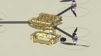
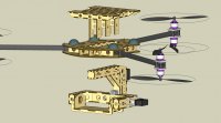
The problem is i cant find any pulleys that would attach direct to a servo that are of the power grip profile you mentioned.
With a tensioner on the belt do you think the backlash will be an issue?
Nobody ever said this was easy, did they?
")
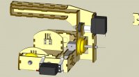
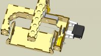
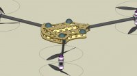
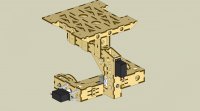
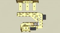
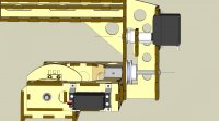
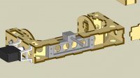
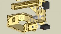
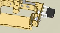
Given that you shouldn't be using the servo's shaft to support the radial load imposed by the belt's tension, the solution to that provides the solution to the attachment issue, too. A shaft, mounted on two ball bearings, either one each side of the pulley or spaced on one side with a cantilevered shaft. The servo should be mounted so that it has no radial load on it. You clamp the servo to the shaft with one of
these. Bearings, bearing blocks, shafts, etc. from Misumi (in suppliers list).
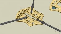
Belt tension has little effect on backlash. The problem with MXL (and its like) is that the square tooth profile means there's only the leading face of the belt tooth in contact with the trailing face of the pulley tooth. There's a gap between the trailing face of the tooth and the leading face of the next tooth. So when the servo reverses, that gap
is the backlash. A round-toothed profile means there's no gap (effectively), so when the servo reverses the belt tooth can "roll" within the pulley profile and take up the drive in the opposite direction "almost" seamlessly.
This is a definite example of the 80/20 rule. The last 20% between "okay" and "excellent" will definitely soak up 80% of your time/budget