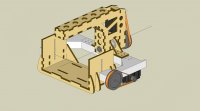
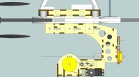
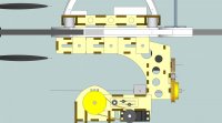
Admittedly my first ideas about positioning the Camera on the Gimbal was to make the Roll pivot axis run through the center of the lens so as when the camera a rolls the lens doesn’t move through an ark. I was thinking in a similar way for the pitch axis.
What I realize I need to do now is try to make the camera move about its CoG. This would make life easier for the servos as well. What I also need to do I s make sure the Camera CoG is worked out when it is mounted to the Camera base plate. The only way I think I can do this reliably is trial and error. Get the camera base plate mounted onto the camera and then physically balance it to find the CoG. I think the best way to do this is on the actual mount its self with no servos connected and somehow make all the pivot points adjustable.
The big problem is when you change something! If you change the lens on the camera it will totally throw out the CoG on the pitch axis, probably not the roll axis so much.
And even more so if you swap your SLR for a Go Pro!!
There are two solutions to this problem I can see. You make a different camera mount for each camera and lens combination. This way you would get optimum performance but it will end up costly and time consuming to design all the different mounts for all combinations possible. Or you make the camera mount adjustable. As Bartman pointed out before, as soon as you allow for adjustments you are allowing for unwanted movement and reduced stiffness.
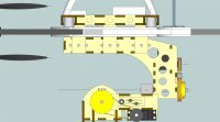
The left/right balance of the camera (roll axis) includes the entire roll axis, remember. You have the servo on the "light" side, which is absolutely ideal: the CG point of the camera is (usually) just to the left of the lens (from the front), so the servo/pulleys/belt/etc. to the right of the camera will shift the effective CG point to (hopefully) dead-centre on the lens. I agree that's desirable (and it's how my own design is set) since you don't want rotational roll compensation to introduce a translation element. By the same token, the pitch axis would ideally be pivoting the camera on a line with the film sensor, but that's inevitably some distance behind the CG point. Some compromise is necessary - I would favour optimum balance over optimum pivot positioning (because I'm mostly interested in stills, where all of this matters less), but if someone was seeking optimum video performance then a solution to that issue could be generated.
Changing lenses will indeed change the balance. The effect might be more pronounced when using a super-light plastic-bodied prosumer DSLR with a heavy lens (compared to a metal-bodied pro camera where the body is likely to be considerably heavier than the lens). I don't suppose the balance has to be spot-on perfect, but this is probably further justification for having the "torquey-est" servos you can find: having buckets of "spare" torque should enable them to "shrug off" small imbalances.
Changing cameras, especially for something as light (and horrible
")
) as a GoPro - well, are you really going to do that? In my own case I've reasoned that I won't - but if I do then I'll substitute the entire camera plate.
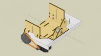
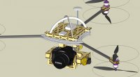
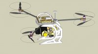
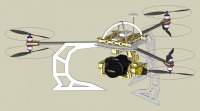
The next issue is the COG of the complete camera mount and camera as a whole. I would always assume that this COG would be best positions directly under the Center of thrust on the main airframe. The COG of the main airframe should also line up with the center of thrust.
This can easily made adjust able fore and aft and side to side so I’m not too concerned about that.
Jess please can you explain what you mean about the thrust lines on a Quad being different to that of a Y6? I’m not sure what you mean.
As mentioned before I always assumed that the center of thrust would be the center where the intersecting lines from each motor
I has also always assumed that the COG of the entire rig should also converge on the center of thrust??
It's the propeller plane that's important - the centre of thrust is the centre-point of a circle connecting the rotational centres of the props (on a flat layout), or the average of the two planes on a coax setup. In an ideal world, the centre of thrust should be coincident with the CG point of the entire aircraft. This would produce the lowest possible moments of inertia on each axis and therefore the most responsive behaviour. In reality some vertical (Z-axis) deviation is perfectly acceptable, but
too much is bad, as previously discussed. Best advice is to keep the vertical CG point "as close as practically possible" to the centre of thrust point. Deviation on the X and Y axes should also be avoided but again it's not hyper-critical. Most craft will fly quite happily with some X/Y deviation but in doing so the work is spread unevenly between the motors - the total power consumed should remain the same but the average power consumed by each motor will be different, which could cause problematic heat/wear issues in an extreme case.
SketchUp Vs Solidworks!! That’s fighting talk!
Yes Solid works is very powerful software and i have used it in the past but for the cost difference and the ease of use then SketchUp wins hands down. In my mind. I then use AutoCAD to prepare the 2D Drawings to send to the Laser Cutter.
I agree - it took me a year to get up to speed with Solidworks, but now I'm glad I persisted. One of its (many) truly invaluable features is the ability to see the weight, CG and MOI of any part, sub-assembly or the entire model at the click of a mouse.
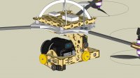
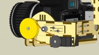
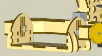
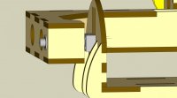
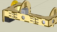
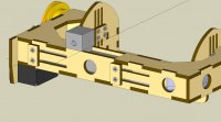
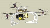
I can see a double bearing block on the roll axis of your model. Are you intending that to be a custom machined part?
Misumi has such blocks in aluminium - many variations, configurable dimensions, etc. - an invaluable source for many precision parts.
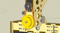
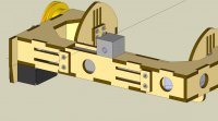
You haven't drawn any mounting mechanism for the servos yet. Timing belts need to be correctly tensioned to perform within spec (slippage, backlash, etc.). Most mounts only allow for tension adjustment (and fitting/removal) by moving the servo position in slots. Personally I don't like that solution - difficult to control and it weakens the mounting rigidity of the servos. A tensioner (which can be a simple idler mounted in a slot to bear against the back of the belt) is, IMO, a much better solution. Also, you have your belt tension supported entirely by the output shaft of the servo. That will "work" but the wear rate on the servo's internals is likely to be accelerated. I'd look at ways of introducing an external bearing to take the strain.