Building a Mikrokopter a' la carte (from parts, no MK kit purchase)

Bartman

Welcome to MultiRotorForums.com!!
doubtful but I'm trying! My wife's family arrives in town today for a two week stay so I may get caught up in that plus I just haven't had the steam to go go go late at night like I used to. We'll see.
I may be in Houston this weekend for training so I'll give a call when I find out.
@ flyeye.....big is right....I don't think it's going to fit in the trunk of my Honda Civic like my MK Okto does......hmmmm......may need to think about my next (used) car.


Bartman

Welcome to MultiRotorForums.com!!
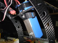
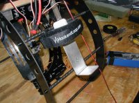
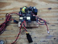
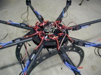
I've been in the basement getting the flight control ready to mount to the frame. In the pics you can see the foam heat-shrinked to the pressure sensor and you might not see it but there's a glob of hot glue under the sensor so it can't vibrate and break the prongs. This happened to my first MK board, caused a crash, and now they're saying to do it as standard practice over at MK.us since the XL MK's are seeing more and more of it happening also. I tried to find the least dense foam I could so it wouldn't impair the sensor's ability to pick up on very small changes in pressure which should result in better altitude hold performance. If ambient air pressure can't be sensed at the tiny hole in the center of the sensor then the FC can't control altitude as well. Leave the hole completely uncovered though and any airflow inside the dome could confuse the sensor.
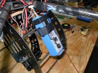
I've got wires for the Spektrum diversity board which will allow me to use multiple receiver satellites and two leads from the top SV2 position for my LED's (red for the front, white in the back). The last spool of wire with nothing on the end will go to a low voltage beeper which I won't be able to hear but at least when I get to the crash site, if it's still beeping, I'll know what happened.

View attachment 543

QUESTION oh MK gurus......
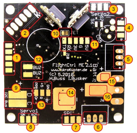
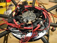
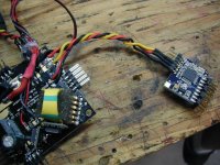
Since I'm not using an MK power board, I assume I need to bring power to the flight control board somehow. Do I just bring full battery (4S LiPO) power to the big pads at 14 and 16? 16AWG wire ought to do, no? I'd bet my little stash of 20AWG servo wire would do just as well actually since it's only powering the brains and LED's (and the not-so-loud beeper).

FlightCtrl_ME_2_1


14 - Ground (GND) connection for the Flight Controller
15 - Positive (+) connection for the Flight Controller (if a power switch is being used)
16 - Positive (+) connection for the Flight Controller (without a power switch)


In looking at how the Molex connector replaces battery connection directly to the FC board, it's amazing to me that the tiny wire in the molex connector brings power for the FC and the two RECOM which power the servos. That seems like a lot of current for such a tiny wire.

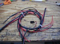
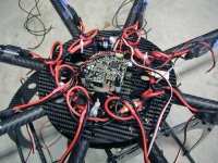
Back to work building my power harness while I wait to see what needs to be done with the FC battery connections.

Thanks,
Bart
 

Attachments

  • P1010021.jpg
    P1010021.jpg
    145.7 KB · Views: 428

FOX222

Member
Bart,
I agree with you on the molex thing. I was very concerned with the connector much less the tiny wires. Even thought I have the MK power ring I chose not to use the molex because of these concerns. If one was to use a big camera mount with a heavy camera I could see the molex having a meltdown.
The FC should use at least 20 awg with a connector rated at least 3 amps.
Yes the FC is powered straight from the battery.

John
 

Bartman

Welcome to MultiRotorForums.com!!
Thanks John. I've got 10AWG for the power loop feeding the ESC's and 16 AWG for the ESC branches so I'll just use the 16 to the FC. Thanks for the reply! I'm planning to put my currently flying Okto into maintenance when this new one is up and running and the list keeps getting longer as far as what I plan to do to it. It's amazing how much you learn when you're not just throwing a kit together per the plans!! One tiny wire in a Molex connector for the FC and all accessories!! Unbelievable!
Moving right along, I ordered the last of the accessories I'll need like a gentLED control for the camera and two Hitec servos for the camera mount. The FC is just about ready to be mounted and I'm well into assembling a power harness for the batteries, ESC's and FC. I've also decided on where I'm going to mount my batteries and that will be the subject of a post in the not-too-distant future.
Bart "need more sleep" C.
 

RTRyder

Merlin of Multirotors
If the servos you are using on the camera mount are capable of drawing more than 1 amp each, which is pretty much any servo used for mounts bigger than the Hisight II, then you should NOT be using the circuitry on the flight controller to drive them. The recom used on the power circuit for the servos is a 1 amp device and the servos on something like an AV200 can draw up to 3X that each. Best practice is to use something like the CC BEC, a voltage adjustable standalone power regulator with a 10 amp current draw capability to drive the servos and have just the control signal coming off the servo port on the flight controller. I made that change on my stock Hexa with AV 130 mount and it made a huge difference in the tilt and roll compensation speed.

Bottom line is you shouldn't need anything larger than servo wire to power the flight controller board. Worst case it's not capable of drawing any more than 2 amps due to the recoms in use so the molex connector and cable can handle the job just fine.

Ken
 

Bartman

Welcome to MultiRotorForums.com!!
Thanks for the input Ken. I'm also in the process of trying to decide what to do about my ESC wiring. The power leads on them are kinda short but I'd like to avoid a solder joint mid-run so I'm considering pulling the power wires from the ESC's and soldering my harness wires directly to the boards where the wires were. more work but i think a neater installation
 

FOX222

Member
The Molex specs sheet on that connector rate it at 1 amp. So you can use it if you feel lucky.

I don't trust the connector even for low current applications on the MK as it was not designed for hi vibration environment. It's a cute little connector but I don't think they gave a lot of thought to this before implementing it in the FC. If you think about the result of even a microsecond interruption in one of those wires and the whole thing is going in so I'm not willing to risk it.


Bartman

Welcome to MultiRotorForums.com!!
my wife has the kids at her mother's house so i've been in the basement all day enjoying my last day off before starting duty tomorrow. finished powering the ESC's and mounting them to the booms. next comes sorting out the I2C/PWM converter.

as far as the power harness is concerned I took two lengths of 10AWG wire and attached deans plugs to the ends. then i toyed around with ideas about where to mount the batteries and how to route the wires. with that decided i then looped the wires so they tied into each other so i'd end up with two battery terminals each feeding the 10AWG loop from either side. i did this for redundancy so i'd have two independent battery connections rather than one with a parallel Y cable like my other MK. so the 10 AWG loop is fed by two batteries and there are 8 16 AWG branches soldered onto the loop for the individual ESC's. I also pulled power with 20AWG wires and servo plugs for the FC power. power to the FC will only have to power the FC/NAVI/GPS boards and the LED's (edit: and the gentLED for the camera since it needs 5v).

View attachment 569View attachment 570

If I get props in the mail tomorrow then maybe we can fly this weekend for the first time.

Bart
 

Attachments

  • P1010028.jpg
    P1010028.jpg
    149.7 KB · Views: 433
  • P1010026.jpg
    P1010026.jpg
    144.4 KB · Views: 287


Bartman

Welcome to MultiRotorForums.com!!
Macsgrafs,
The standoffs come from the MK dealer although there are probably other places to get them. Get four of the 8mm long black rubber ones as well for the bottom of the stack. There are longer rubber ones but I think they're too much so I use the short ones with a plastic 5 or 8mm one on top of each before mounting the FC.

The pic shows the connections for the I2C to PWM converter. The instructions say you can use a servo connector but I opted to solder everything. Thank you to the heavy duty servo extension that gave its life so i could use twisted wires everywhere.

edit, after wiring the converter to the FC I found out that you can't calibrate the ESC's while the FC is attached to the converter so it's been undone and I'll use a servo connector like the instructions say to do.


View attachment 575

Moving right along, today I'm hoping to have the motors connected just in case the props arrive in the mail later on. Have to see the Dr. at 1:15 about an achy ear so there's that to tend to as well.


Commentary: With all the work involved in going the I2C/PWM route with ESC's and wires seemingly everywhere, I'm not so sure I'd do it again on an 8 rotor. It's just a lot of work and it isn't quite as elegant as the MK power board. It's amazing in building all of this how many tiny solder connections there are where failure of any one of them can be game-over. My first MK was ARF'd by Ziggy and I was in such a state of amazement with it that I didn't notice so many of the tiny details. This build though has me intimately involved with all of them so it's a real eye opener. There's a conversation in another thread about quality vs. redundancy and I'm ready to vote, I'll take BOTH!
 

Attachments

  • P1010030.jpg
    P1010030.jpg
    148.9 KB · Views: 389


Emowillcox

Member
Hey Bart do you have a photo of the gentled device is that one of the light camera triggering devices? Also what is the clear material your using to hold your escs to the frame?
 

Bartman

Welcome to MultiRotorForums.com!!
Mike,
The gentled device is available from either MK shop in the US now. It's really simple, a servo wire, an IR generator, and an IR LED. It needs 5V power so it can just be plugged into a FC with servo outputs and it's ready to go. The one rub is that it needs a three position switch to work for the 550D so you've got to have one available on your radio to be able to do stills and video in the same flight. Thanks to the mighty Droider for pointing me in that direction.

Here's the manufacturer's link
http://www.gentles.ltd.uk/gentled/liveview.htm

The clear material is regular 3M vinyl tape. It's about $2 at hardware stores but I'm pulling it off and replacing it with regular old black electrical tape. That tape is going to collect all sorts of dust and dirt and, since it's clear, it'll look like hell before too long. It would be nice if I had little flat mounts that sit tight on the round tube so a small zip tie could be used. I may try to make something that can be glued to the arm for the ESC's to sit against or maybe velcroed to. I don't love the way it is with the tape.

I posted in the general discussion area about getting the ESC's sorted out.
 

Emowillcox

Member
okay i'll have to check out the gentles device.. i use one of their timers to trigger a servo and fire my camera..
I used velcro and zip ties in the past on the escs and had pretty good success
your right it won't take long for that clear tape to get dirty
 

Mactadpole

Member
just finished the power harness, the servo connector is for the power to the FC. next comes the connections to the ESC's. View attachment 1076View attachment 1077

Hey Bart,

I noticed both + and - loops of your power harness are connected (complete circle). I was informed a while back that this can cause noise in the power lines. The best way to eliminate the noise is to not have the negative complete the circle. On one of my hexa's I had it make a complete circle and never had a problem, but from there on I have never had the negative form a complete circle. It may not be an issue for you but thought I would pass the knowledge on that was bestowed upon me from some folks who know about electricity.

Looking good!

Best,

Shawn
 

Bartman

Welcome to MultiRotorForums.com!!
Things are moving along and I'm about ready for a first flight. Given the nature of my flying lately I thought I'd post a few pics before the flight rather than after.

Here are the battery mounts for two 5000 mah 4S Lipo packs, one on each side. The goal is to have a battery slip out the bottom of the mount in a wreck rather than stay attached and have it's weight do damage to the frame. This has worked pretty well with the flimsy plywood mounts I made for my MK Okto.
View attachment 653View attachment 651View attachment 652
 

Attachments

  • P1010052.jpg
    P1010052.jpg
    140.6 KB · Views: 374
  • P1010051.jpg
    P1010051.jpg
    148.5 KB · Views: 362
  • P1010050.jpg
    P1010050.jpg
    146.4 KB · Views: 385

Macsgrafs

Active Member
They look great Bart, shame I cant do that to my CS8...my camera mount is controlled bu a camera op & she has to be able to swing the camera, but for a fixed forward camera this is great.

Ross
 

Top