Gunters new octocopter build

jes1111

Active Member
One other thing - pos/neg wires from battery to ESC should always be (lightly) twisted, and the three wires from ESC to motor should always be (lightly) twisted. Some people like to braid the three wires, but IME that results in a very bulky result.

Use little pieces of heat-shrink at intervals to stop it untwisting.
 

Gunter

Draganflyer X4
One other thing - pos/neg wires from battery to ESC should always be (lightly) twisted, and the three wires from ESC to motor should always be (lightly) twisted. Some people like to braid the three wires, but IME that results in a very bulky result.

Use little pieces of heat-shrink at intervals to stop it untwisting.

What's the reason for the twisting them?
 

jes1111

Active Member
It cuts down on radiated EMI from those wires - something to do with little magnets cancelling each other out ;)
 

jes1111

Active Member
btw... the twisting thing applies to servo wires and the wires between Rx and FC as well as the wires between FC and ESC. Most hobby servos come with three-conductor ribbon cable simply 'cos it's cheaper and easier for them to make it that way. Carefully separate the three wires then twist them together - saves a lot of "servo glitches" apparently :)
 

DucktileMedia

Drone Enthusiast
Interesting on the wires. I see you had a cad drawing of a hex. Is there any reason one would make one arm forward instead of the 2 arm forward configuration? Any advantages from one to the other?
 

Gunter

Draganflyer X4
Interesting on the wires. I see you had a cad drawing of a hex. Is there any reason one would make one arm forward instead of the 2 arm forward configuration? Any advantages from one to the other?

It just depends really on your camera, + configuration might mean that you see the arm in the video where an X configuration means there is less for the camera to see.
 

DucktileMedia

Drone Enthusiast
I would just assume you would always want the Y forward and not an arm direct in front.

So i bought a bag of Molex connectors that are 3 circuit. I was planning on not using the typical bullet connectors as when you detach an arm there are 3 wires to get right. I never understood why we dont use something like this. I see in your cad drawing you had this same idea. Are we missing something? Maybe vibration issues or poor conductivity.

http://www.molex.com/molex/products...003091031_CRIMP_HOUSINGS.xml&channel=Products
 

DucktileMedia

Drone Enthusiast
Looking good!

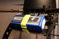
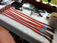
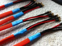
I've researched this "ESC wires" issue as thoroughly as possible. Trouble is, of course, that you can find reasoned, scientific arguments both ways! However, after weighing all the evidence, my conclusion is to keep battery > ESC short and ESC > motor can be lengthened to suit your frame.

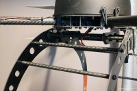
I, too, detest the idea of strapping the ESCs to arms. It looks ugly, plus they're vulnerable to damage and subject to all the vibration that's travelling through that arm. I also don't go with the argument that they need to be cooled by the propwash. If they need that much cooling then they're either under-rated for the job or something else is wrong (like the timing). The best advice I've seen on ESC sizing (by a dealer who has to field warranty claims for burned out ESCs) is to over-spec by 50%, i.e. if eCalc says your full-throttle draw will be 37A, fit 60A ESCs - not 40A units.

Of course the ESCs still need airflow, so certainly don't put them inside a box (which I've seen done). If you do have a minor heat issue and/or want more peace of my mind over their health and longevity, fit each one with one of those miniature fans used on PC motherboards - they weigh just a couple of grams.

One thing I believe you should NEVER do (on anything but the small fun-flyer types) is use the BEC on the ESC. They're often linear BECs on the cheaper ESCs (which simply drop voltage by using resistance and therefore generating heat), and since you'd only be using the BEC on one out of your 4, 6 or 8 ESCs that ESC will run hotter than the others - not a good design choice. A good quality switching BEC can supply all the necessary low voltage to your FC, Rx, servos, etc.

This has me concerned using my BEC ESC. When you have multiple ESC's with a BEC how does that effect the voltage to the FC/Receiver? I am assuming it ends up in parallel and not series. that would be really bad! but the better question, is how do you NOT use the BEC? Cut the wire on the leads? There arent many ESC's availble without a BEC these days. I got the Maytech 30amp from MontoRC as I got the Avrotos from there as well. Any input would be greatly appreciated as I am close to wiring this beast up.
 

jes1111

Active Member
This has me concerned using my BEC ESC. When you have multiple ESC's with a BEC how does that effect the voltage to the FC/Receiver? I am assuming it ends up in parallel and not series. that would be really bad! but the better question, is how do you NOT use the BEC? Cut the wire on the leads? There arent many ESC's availble without a BEC these days. I got the Maytech 30amp from MontoRC as I got the Avrotos from there as well. Any input would be greatly appreciated as I am close to wiring this beast up.
There's no problem with having a BEC on each ESC, just don't use them if you want maximum reliability ;) - As you say, remove or cut the red wire. (If you do use a BEC, you should only use one, so remocve/cut the red wire on all but one. Nasty electrical things can happen if you have multiple BECs connected to your Rx/FC.)

Much safer, more reliable alternative is a good switching SBEC like the Castle Creations BEC Pro, to power FC,Rx, servos, lights, etc.
 

jes1111

Active Member
I would just assume you would always want the Y forward and not an arm direct in front.

So i bought a bag of Molex connectors that are 3 circuit. I was planning on not using the typical bullet connectors as when you detach an arm there are 3 wires to get right. I never understood why we dont use something like this. I see in your cad drawing you had this same idea. Are we missing something? Maybe vibration issues or poor conductivity.

http://www.molex.com/molex/products...003091031_CRIMP_HOUSINGS.xml&channel=Products
Would need to know how much current you're intending to pull through those Molex. My guess is their going to overheat. :(

Something like this would be a better bet: http://www.astroflight.com/index.php?main_page=product_info&cPath=18&products_id=37
 

Borneoben

Member
Or you could use Anderson Power Poles!!

You can assemble 3 togetehr side by side very easily!

I may incorporate that into my next Design!

Thanks for the idea

Ben
 

DucktileMedia

Drone Enthusiast
The Molex connectors i bought are 12 amps, but I dont know if that is per lead or collectively. I may just end up soldering everything as I dont see a convenient way to detach the arms anyways.

Great tips on the BEC's! thanks. I just need to decide if i can wait to get a separate BEC or just use 1 of my 6.


Gunter

Draganflyer X4
Great looking build Gunter! If you need any of those motor mounts cut from Black delrin I would love to give it a shot.

Chris, do you mean the mounting plates or boom clamps? If you mean boom clamps, that would be extremely helpful! The boom clamps I have managed to find cost £5 per set of 4, not too bad, but have to be specially ordered from the USA which will take another 3 weeks. This is probably also something you could sell to others as well, because they suit a standard 3/4 inch tube...let me know if you want a drawing!
 

Gunter,

The mounting plates would be a piece of cake, well the bottom one would be tricky, unless you know how to form thermoplastic. If you want, send me a drawing of the parts, and I will see if I can do the Clamps as well.

I'll PM you my email addy.
 

drhswe

Member

Attachments

  • 1_800.jpg
    1_800.jpg
    136.5 KB · Views: 390
  • 2_800.jpg
    2_800.jpg
    145.2 KB · Views: 412
  • 3_800.jpg
    3_800.jpg
    145.3 KB · Views: 421
  • 4_800.jpg
    4_800.jpg
    136.3 KB · Views: 399


Gunter

Draganflyer X4

Attachments

  • IMG_0412.JPG
    IMG_0412.JPG
    143.4 KB · Views: 459
  • IMG_0413.JPG
    IMG_0413.JPG
    146.3 KB · Views: 411
  • IMG_0414.jpg
    IMG_0414.jpg
    146 KB · Views: 314
  • IMG_0415.jpg
    IMG_0415.jpg
    138 KB · Views: 285
  • IMG_0416.jpg
    IMG_0416.jpg
    146.5 KB · Views: 410

Gunter

Draganflyer X4

Attachments

  • IMG_0417.jpg
    IMG_0417.jpg
    143.1 KB · Views: 376
  • IMG_0421.JPG
    IMG_0421.JPG
    136.6 KB · Views: 320
  • IMG_0422.JPG
    IMG_0422.JPG
    121.9 KB · Views: 282
  • IMG_0423.jpg
    IMG_0423.jpg
    134.5 KB · Views: 330
  • IMG_0424.jpg
    IMG_0424.jpg
    133.8 KB · Views: 312


Top