AV200 + brushless

milo12

Member
Hi!
I think-its good! With 160 poles on roll and 64 poles on tilt and pan axis I found good setup for Sony CX730 camera. But with Canon 5D MkIII and 50 mm objectiv I have a trouble with COG. I cant move 5D enough to the side (oposite of pitch motor), to find good position. Maybe at extreme right is possible, but than cant connect HDMI or AV cable to cammera. I think, maybe with larger lens, but I dont need it...

Does the centering problem hurt the performance? I thought the reason for IDD is it is way more tolerant of bad balance.

Any sample videos?

Sent from my Transformer TF101 using Tapatalk


Droider

Drone Enthusiast
Does the centering problem hurt the performance? I thought the reason for IDD is it is way more tolerant of bad balance.

Any sample videos?

Sent from my Transformer TF101 using Tapatalk

They are. I dont know the Alexmoss boards but I will post a video of how tolerant the Carvec system is. There is more info in the following threads

http://www.multirotorforums.com/sho...des-to-G-Lock-and-Brushless-Gimbal-Controller

http://www.multirotorforums.com/showthread.php?15887-G-Lock-First-flight-test

http://www.multirotorforums.com/showthread.php?17634-Wiring-Schema-G-Lock-BLD-3-axis

http://www.multirotorforums.com/sho...ss-Gimbal-Controller-amp-Photohigher-AV200IDD

Dave
 
Last edited by a moderator:

Hi!
I think-its good! With 160 poles on roll and 64 poles on tilt and pan axis I found good setup for Sony CX730 camera. But with Canon 5D MkIII and 50 mm objectiv I have a trouble with COG. I cant move 5D enough to the side (oposite of pitch motor), to find good position. Maybe at extreme right is possible, but than cant connect HDMI or AV cable to cammera. I think, maybe with larger lens, but I dont need it...[/QUOTE
Hi,
Could you please post a video with your results?
Many thanks
 

Hi guys,
Really dont know if the AV200/Brushless is a goer..Can t find one single video on youtube with some disent footage on it:upset:
They all have jitters, all of them. And I would REALLY like to go for it but it ain't seam right.(Hope somebody can prove me worng within the next week..)
A
 

SMP

Member
Working on the AV200 with the Photohigher IDD Brushless Conversion - The Final Kit shows potential and was making progress until the 3 axis Alex board died. Just received another board AND the 32 bit board as well so will put everything back on the bench and start testing again. The IDD kit itself was a genuine pain in the *** and I ended up needing some help. Photohigher was VERY VERY good here and managed to get the gimbal into mechanically perfect condition. (Thank you PH job well done that!)This is an absolute must, there are a lot of mechanical components and everything has to be tight. Using the Alex boards requires a Degree in PID tuning but did manage to get the Roll which I think on the AV200 the most challenging working well. So there is HOPE. Note, HOPE. like many others this has not been a easy process, so Optimism isn't warranted yet but at least I've changed from Pessimistic. We'll see.

I'm also in the process of wiring in the Alex to a Cinestar style RCTimer Legacy gimbal. We'll see if the IDD or the Cinestar Clone win out. In theory IF the AV200 can be tuned then it should be more flexible in balancing and THAT could be the difference. Don't sell those AV200's just quite yet.
 

Hi SMP!
And by the way, that Rc gimbal looks very good
Please let us know your results!!!Good luck!!!
 
Last edited by a moderator:

darekbo

Member
Hi
SMP could you post same of your aerial video with alexmoss ? I am using alexmoss on cinestar bl clone and it works quite good but I have also 2 av200 so I have to chose : I can upgrade them or buy another cinestar bl clone at more or less the same price.
 

SMP

Member
Ok guys, finally had a chance to take the AV200 Brushless IDD out for its first flight. Had a visit from City of Miami while we were setting up. Made a friend but meant the flight was in darkness and the camera wasn't focused. Not really the point though as what we wanted to see was the ability to change direction and tilt without jitter.

What we knew going in.

Hardware: Beta kit was a hot mess. The final conversion kit is perfect. V Drives align (and must be kept tight). Had the tilt v drive shift position and required adjustment. Once adjusted held position. The ROLL ring must be PERFECT with no flex or play. This required us to send to PH to have brought back into spec as we simply didn't have the time. The conversion requires almost complete disassembly of the gimbal. As we were part of the Beta we are on Tiger motors. These motors seem to require GOBS of power in order to get past the cogging. Tons of holding power but the high Power numbers (220) mean less P before oscillation. Latest kits use Maxon. No clue if these are more efficient and can use less Power. Summary. Make sure your gimbal is in mechanically perfect condition.

Software: Tests on the bench have been difficult. Firmware updates dramatically change PID performance particularly I parameter. As mentioned the Roll motor requires high Power settings, this limits P (40) setting which is why the Roll is slow. Using high sensitivity to lower Power and P numbers didn't work. Tried latest FW and kept rolling all the way back to 2.2b before i was able to find Power and P settings that were close on the bench. Going up I knew the Roll would be slow. It is indeed slow but not bad (meaning its smooth) except in the most Violent back and forth movements, further tuning SHOULD be able to find an answer here but this is going to take FW PID massaging.

Off the top of my head (Tigers are 24 pole/Roll is 10x and Tilt/Yaw 4x)
Roll Poles - 240 at 220 Power
Tilt/Yaw 96 at 180 Power

Roll P 40 I .11 D 30
Tilt... Ahh hell dont remember. Less than Roll.
Yaw. 10 something.

Point is, Roll is abominably high.

Flight test: 5D3/24mmIS

Yaw is a hot mess but didn't have it enabled except RC (NO Follow modes inc Yaw) and just barely enough gains to make it rotate. You can see it hang up. Will have to look and make sure I enabled 360 degree rotation OR just ran out of power to swing around and bring back into alignment. Goal wasn't to play with yaw on this one.

Tilt: Gone are the Skyline tilt jitters!!! Tilt works awesome even with 8/10 balance. The IDD system is much more tolerant of out of balance cams. Even under wicked back and forths tilt worked great. There is a horizon roll when tilting 90 and returning 90. Although spent a ton of time getting the IMU PERFECTLY square to tray either i have just the tiniest bit of offset still or this is a bit of alexmos bug. Either way, tilt is a world away from Skyline. SUCCESS!!

Roll: Roll needs even more P! Bit of slow horizon correction as well. However slow horizon correction is due to pulling I down low to give more overhead for P and D. Roll is slow but in truth I'm hauling this full right/full left. If the Roll ever catches up this will be perfect. Again, NO MORE SKYLINE TYPE JITTER ON DIRECTION CHANGE!! SUCCESS!

Test video here, look at frame edges, no jitter. So, not quite there yet but it will work. For a first flight I'm pleased. Don't sell that AV200 after all. Three years and finally hope!

https://www.youtube.com/watch?v=ldjZsmukK4w
 
Last edited by a moderator:

Thanks SMP for your time and efforts!
Still needs some work but its looking beter,¡
Needs more torque on the motors?
 
Last edited by a moderator:

SMP

Member
Aye, needs more torque on roll. Find more torque and you've got gold. The video is a trainwreck but what ISNT there are the Skyline jitters on direction changes and that means once the PIDs are dialed in the gimbal will work.
 

SMP

Member
Ok Test 2 with the AV200 Brushless - What it is. A ton of yanking the jib full back and forth, forward and back. Roll is still slow but gone are the skyline jitters on direction changes. Didn't disable the yaw which is complete **** and didn't have a camera op so it flops horribly (also demonstrates why you don't do whip pans with dslrs) 5D3w24mm no post stab (clearly)

http://youtu.be/PJVzDuLF9ds

Conclusion - it works way better than the Skyline and demonstrates that the conversion does work; (just needs someone with more time to test). Next steps, up the roll Power again and fix the bloody yaw. Convert the other AV200.


Mojave

Member
Need Help with the 360 Pan IDD Build Instructions

Help! I am have an AV200 IDD I bought awhile ago from PhotoHigher. They sent out the IDD gimbal assembled; with a Pan Kit unassembled. The documentation on the assembly of the Pan Kit is not clear to me: http://photohigher.com/assets/Uploads/AS-013-AV200-IDD-Conversion-Assembly-Instructions.pdf The photos and instructions lack the detail of the previous documents for the standard serveo AV200 (http://www.quadrocopter.com/assets/templates/quadrocopter/downloads/assembly_AV200-360pan.pdf or this one http://www.photohigher.com/assets/Uploads/AV200-2360MR-Build-Guide.pdf). I need an exploded view or an illustrated series that shows if the thrust bearing is actually sitting on the second bering on top of the gimbal housing.

I can make educated guesses; but I should not have to with this quality gimbal. Any assistance would be appreciated.

Thanks for the assistance - Cheers!
 

Mojave

Member
AV200 IDD 360 Pan Kit Assembly Figured Out

Help! I am have an AV200 IDD I bought awhile ago from PhotoHigher. They sent out the IDD gimbal assembled; with a Pan Kit unassembled. The documentation on the assembly of the Pan Kit is not clear to me: http://photohigher.com/assets/Uploads/AS-013-AV200-IDD-Conversion-Assembly-Instructions.pdf The photos and instructions lack the detail of the previous documents for the standard serveo AV200 (http://www.quadrocopter.com/assets/templates/quadrocopter/downloads/assembly_AV200-360pan.pdf or this one http://www.photohigher.com/assets/Uploads/AV200-2360MR-Build-Guide.pdf). I need an exploded view or an illustrated series that shows if the thrust bearing is actually sitting on the second bering on top of the gimbal housing.

I can make educated guesses; but I should not have to with this quality gimbal. Any assistance would be appreciated.

Thanks for the assistance - Cheers!

I answered my own question with the documents above for the old style gimbal and Droider's photos here: http://www.multirotorforums.com/sho...ss-Gimbal-Controller-amp-Photohigher-AV200IDD.

Sorry if the following is a tad off topic but I feel it is important to record it somewhere; it would have helped me. I will add this in my build thread as well (http://www.multirotorforums.com/showthread.php?19613-New-Build-HexaCrafter-1100L-Heavy-Lift).

These instructions refer to the following items (from my invoicing):
PhotoHigher: 001-0060 AV200 IDD Standard DroidWorx 360 Pan Kit - NoSkids and 000-1010 AV200 IDD 2 Axes Brushless Gimbal Assembly mounted on the gear rail of DroidWorx (Aeronavics) 4404-0041-XM Landing Gear and Gear Rail Assembly Retractable Ti - Extended. It finishes off with about 3/4 inch (20mm) clearance from the deck.

For a partial list of terms see the original AV200 Pan IDD conversion instructions (http://photohigher.com/assets/Uploads/AS-013-AV200-IDD-Conversion-Assembly-Instructions.pdf) and the list here - http://www.quadrocopter.com/assets/templates/quadrocopter/downloads/assembly_AV200-360pan.pdf.

The pan head assembly sequence and abbreviated instructions follow:

1) Remove the DroidWorx Camera Mounting Bracket Assembly from the Gear Rail Assembly. Remove the DroidWorx Camera Mounting Bracket from the rails. Later this will be replaced by the modified PhotoHigher Gimbal Mounting Bracket with gimbal. In the PhotoHigher 360 Pan Kit remove the two aluminum DroidWorx adapter plates (one has PHOTOHIGHER carved into it and other is shaped similarly but nests inside the larger plate. The smaller plate fits perpendicularly inside the larger plate; screw them together with 3mm nuts and bolts in the preexisting holes – this unit is the PhotoHigher Gimbal Mounting Bracket. Fit the grommets into the holes in the Gimbal Mounting Bracket. Put this aside.

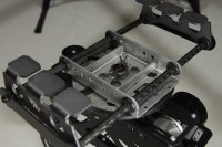
2) Push the Bearing + Flange up into Bottom Bearing Bracket (bracket tabs point down - push the Bearing + Flange hard, use a flat surface like a small square piece of wood and push evenly and firmly). Screw the bracket into the gimbal using the mounting holes. Push the second Bearing + Flange onto the center hole on the top of the gimbal (push firmly and evenly down or turn the gimbal over and push on the same surface used previously). Insert the Pan Axis Bearing Spacer (small aluminum cylinder) between bracket and the inside of the top of the gimbal (a tight fit) it will rest between both Bearing + Flanges. Push the Pan Shaft up from the bottom of the Bottom Bearing Bracket, from inside the gimbal housing, and through the top of the gimbal and the top Bearing + Flange. Temporarily hold the shaft in place with tape at the top of the gimbal.

3) Locate the Pan Motor Assembly and maneuver it into the top of the gimbal – screw it loosely into the cut out at the top of the gimbal. Screw the V Pulley onto the top of the Shaft on the Pan Motor Assembly. Later the assembly, shaft or pulley will need to be adjusted as well as the pressure that the V Pulley exerts on the V Disc.

4) Carefully remove the tape holding the shaft and hold it up in place from the bottom. Place the Thrust Bearing (wide ring of needle bearings with a hole in the center) over the Pan Shaft on top of the gimbal housing. At this point the bearing may be lightly lubricated. The shallow aluminum cylinder (Thrust Bearing Cap) has an indentation, this fits over the Pan Shaft and rests on the Thrust Bearing. The V Disc has a recess that fits over the Thrust Bearing Cap. The V Disc Spacer fits on top of the V Disc.

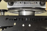
5) Get the Gimbal Mounting Bracket (step one above) and place it on the V Disc Spacer. Place the aluminum washer over the end of the shaft and place the lock nut on the shaft, tighten just enough to hold everything firmly and place the Spring Pin through the holes in the shaft.

6) Make sure the V Pulley and V Disc are even and snug just enough to run freely. If they need adjusting disassemblely may be required to adjust the motor or shaft. Once all parts run smoothly by hand tighten up all parts including the top of the shaft and place the Spring Pin in place.
Place the Gimbal Mounting Bracket on the old DroidWorx Camera Mounting Bracket rails. It is now a PhotoHigher Gimbal Mounting Bracket with gimbal. Mount this gimbal assembly and it should be securely mounted onto the multirotor. Using the grommets the assembly may be adjusted fore and aft to balance the center of gravity of the multirotor.

The images illustrate approximately: Step 2, Step 5, and Step 1 and 6 together, respectively.

View attachment 18904View attachment 18903View attachment 18902
 

Attachments

  • Cotter Pin - Pan Shaft - Lock Nut - Al Washer - Unknown Tray - Droidworx Adpater Tray (IMG_8438).jpg
    Cotter Pin - Pan Shaft - Lock Nut - Al Washer - Unknown Tray - Droidworx Adpater Tray (IMG_8438).jpg
    131.7 KB · Views: 278
  • V Disc Spacer - V Disc- Thrust Bearing Cap - Thrust Bearing - Bearing and Flange (IMG_8426).jpg
    V Disc Spacer - V Disc- Thrust Bearing Cap - Thrust Bearing - Bearing and Flange (IMG_8426).jpg
    125.6 KB · Views: 231
  • Pan Axis Bearing Spacer - Bottom Bearing bracket - Bearing and flange - Pan Shaft (IMG_8360).jpg
    Pan Axis Bearing Spacer - Bottom Bearing bracket - Bearing and flange - Pan Shaft (IMG_8360).jpg
    125.9 KB · Views: 249


Top