Some more questions:
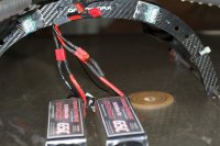
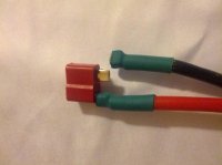
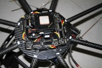
(1) I have to ask - what's the shiny deposit around one of the battery connectors in the photographs? Is it something you applied or did that leach out of the connector/wire?
(2) I'm guessing this rig pulls around 150A at full throttle - so that's certainly exceeding the maximum rating of a Deans connector. After a flight have you checked temperatures with your fingers? Is one of the battery connections hotter than the other, particularly when this uneven drain occurs? Are the wires hot anywhere?
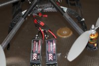
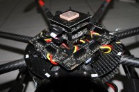
(3) You are using a Y-piece parallel adapter, feeding into a single cable. Where does that cable go to? i.e. does it go to a Power Distribution Board from which the ESCs are fed or does it split out from a soldered junction to go to each ESC? If it's a PDB then brand/details and a photo will help.
(4) Wire gauge - I can see the markings on the battery cables (10AWG) and the final piece of the Y-piece (10AWG) but the two branches of the Y-piece look like they might be thinner (12AWG?). Please confirm. Also please confirm the gauge of the wire from the single master connector onwards.
In the meantime I'm pulling together the list of part numbers for the relevant parts - you're right: it's not easy with so many choices
")
I'm asking these questions because with that kind of amperage I think we need to alter your wiring scheme a bit rather than just replace the connectors.