AzViper
Active Member
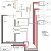
I am in the process of getting my parts list together. The wiring diagram below is from a member of these forums. I have removed items and added what I believe will work. The power distribution board is for the ESC’s and the power to the NAZA. The second adjustable voltage PDB will be just above the PDB to step down the 6s battery to 12v and 5v for the TX and 3 axis gimbal.
I had planned to use KDE 4014XF-380 motors and KDE ESC’s but the expense has reversed my thinking. I am now going to use Tiger Navigation Series MN4012 400KV motors with SimonK 30A ESC’s using a 6s 10,000mah battery.
Please give me your thoughts whether positive or negative. I am new to quads and your input will help direct me in the right direction.
Attachments
Last edited by a moderator: