YAY, First Multirotor Build!!!

pootman

Member
Progressing

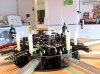
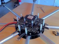
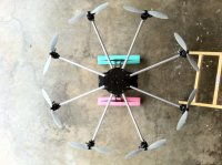
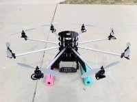
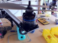
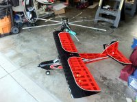
I received my motors today (Avroto 2814 Short Shaft) and they looked like nice quality motors. One of them seems to be turning a little tighter than the others. I did make sure that the motor wires weren't crossing when I turned it. I'll take a closer look at it later. I also cut down the booms. Hope I didn't cut them too short, I really got used to the way the giant booms looked on there.

I ordered a gopro a couple of days ago. Now all I need is the MK stack and FPV /OSD hardware. I've been trying to read up on antenna styles and their pros/cons. Way too much info!:confused:

pootman
 

Attachments

  • 11-07-13_3.jpg
    11-07-13_3.jpg
    147.3 KB · Views: 382
  • 11-07-13_1.jpg
    11-07-13_1.jpg
    148.7 KB · Views: 387
  • 11-07-13_2.jpg
    11-07-13_2.jpg
    142.3 KB · Views: 373
  • 11-07-12_1.jpg
    11-07-12_1.jpg
    146.2 KB · Views: 260
Last edited by a moderator:

Crash

Defies Psychics
I've been trying to read up on antenna styles and their pros/cons. Way too much info!:confused:


Skew-Planar/Pinwheel and cloverleaf. You won't go wrong. Maybe some better ones have been developed in the last couple months though. I haven't been keeping track. Either way, stay away from anything that isn't circular polarized.
 

pootman

Member
Thanks Crash. I've been reading up on antenna designs on the forums and, well, my head hurts. I'll keep circular polarized and Skew-Planar/Pinwheel and cloverleaf in mind when it come time to buy and setup a FPV system. Along the lines of FPV, antenna, and range, how far can you reliably fly a JR/DSM2 radio setup? Or more importantly, how about around stuff (i.e., trees, buildings, etc.)? I'm not planning on flying for distance, but I may end up flying around objects on occasion.

I ordered the bulk of my MK setup today!!! YAY!!!! I also ordered 4 x Turngy 4s 5000mAh 40C lipos. Can't wait to start on the build later this week when I get home from work.:D
 

pootman

Member
Received my MK parts from Quadrocopter!

Hello All!!!!

I received my MK gear today and I've been re-reading a lot of build logs and MK's wiki site. Here's what I have done so far. Does it look right? Also, with 2 caps per BL-Ctrl, does the pic I posted (4th pic) with the caps back to back correct? Lastly, what are the white circles between the caps marked C1, C2, C3, etc...? I tried to find some reference to them but I was unsuccessful. My power distribution board looks a bit different from some of the build blogs and MK's wiki site. Not sure if it's a new design???

pootman
 

Attachments

  • 11-07-21_1.jpg
    11-07-21_1.jpg
    146.6 KB · Views: 366
  • 11-07-21_4.jpg
    11-07-21_4.jpg
    146.3 KB · Views: 369
  • 11-07-21_2.jpg
    11-07-21_2.jpg
    146.3 KB · Views: 362
  • 11-07-21_3.jpg
    11-07-21_3.jpg
    145.9 KB · Views: 403

pootman

Member
A little more progress. The power distribution board did not come with a molex connector so I has to order one today. Think that might be the last thing on this board. Is there a way to update the BL-Controllers after they're soldered on the power distribution board? Thanks! :)

pootman
 

Attachments

  • 11-07-22_2.jpg
    11-07-22_2.jpg
    148.9 KB · Views: 336
  • 11-07-22_3.jpg
    11-07-22_3.jpg
    146.7 KB · Views: 309
  • 11-07-22_4.jpg
    11-07-22_4.jpg
    148.6 KB · Views: 222
  • 11-07-22_5.jpg
    11-07-22_5.jpg
    148.6 KB · Views: 333
  • 11-07-22_1.jpg
    11-07-22_1.jpg
    148.7 KB · Views: 315

Droider

Drone Enthusiast
Is there a way to update the BL-Controllers after they're soldered on the power distribution board? Thanks! :)

Nay.. I dont think so.. make sure you have belled everything out with a MM.. before and after fitting the molex.. which in MO is a totally pants way of connecting the DB to the FC.. but it works for most.. its just a beehatch to do!

Dave
 
Last edited by a moderator:

Droider

Drone Enthusiast
How u done the +/- connections.. It all looks VERY neat but I am puzzled as to what you have done with them.

Dave
 

pootman

Member
Hi Dave!

I soldered the red wire on the top tab marked with + and black wire on the bottom marked -. It does seem to be very close to each other and makes me a little nervous. I slid some shrink tubing over both wires with a small notch cut out to make room for the tab that both wires are soldered to. I've soldered the addressing for each BL-Ctrl and no there's just the molex connector. I have a couple of questions about your post above.

1. What's "belled everything out with a MM."?
2. "totally pants way of connecting the DB to the FC", is that good or bad? I've been reading some of Bartman's build and it sounds like the molex may be unreliable. If I don't use the molex, how would I connect the DB to the FC?

Sorry for all the questions, I'm having a hard time finding this info on the wiki site.

Lance
 

pootman

Member
MK Stack Mock up

I've mounted the DB and test fitted the MK stack. I'm thinking about mounting the GPS on the upper shelf of my rusty's frame. I want to use the upper carbon plate as the protection in case of a crash instead of a plastic cover. However, I'm thinking the upper carbon plate will block the GPS from receiving a good signal. So, I was thinking the DB, FC, and Nav will be on the lower shelf and the GPS antenna will be on top. I'm a little worried about wiping out the GPS if I crash and would like to protect it without degrading it's ability to receive a strong signal. What do you guys think? Good or bad idea?

Lance
 

Attachments

  • 11-07-22_10.jpg
    11-07-22_10.jpg
    148.2 KB · Views: 371
  • 11-07-22_7.jpg
    11-07-22_7.jpg
    147.7 KB · Views: 363
  • 11-07-22_6.jpg
    11-07-22_6.jpg
    144 KB · Views: 430

pootman

Member
Here are some pics of what I described above with the GPS on the top plate. Should I move it back under the top plate? Or leave it above and us some sort of dome to protect it?
 

Attachments

  • 11_07_22_15.jpg
    11_07_22_15.jpg
    145.4 KB · Views: 327
  • 11_07_22_13.jpg
    11_07_22_13.jpg
    146.3 KB · Views: 363

Droider

Drone Enthusiast
Nice work Lance..

I may be inclined to lift the FC up a tad away from all the motor wires..Sandor at Digitech puts a alu plate where you have the fc and lifts the fc up above on another set of standoffs.

http://www.youtube.com/watch?v=7jRXK-JD-gM&NR=1

Belling out with MM.. check for continuity with a multimeter round each 12c line and make sure there is non between them and power.

Dave
 

pootman

Member
Thanks again for the all the help. I still feel a bit like I'm walking around a dark room when it comes to this stuff. I had posted my DB pic on RCG's MK thread and someone pointed out that the octoXL DB board had another set of instructions on the wiki site. Really hard to find! Anyhow, it looks like I put the caps on the wrong side of the board, but the polarity it correct. Not sure if I should try to remove and relocate them as I may do more damage. Also, on the octoXL wiki, there's no reference to the bridge's on the corners of the DB. I was wondering why the bridge connection points were covered with the black paint on the DB. So I took a very small drill bit and uncovered the bridge connection points and installed the bridges. Since there isn't a reference to these on the octoXL DB wiki site, I'll remove them. I just hope removing the black paint covering the holes didn't mess anything up. I'll check for continuity today and do the initial power up test with a 9V battery so I don't fry anything. Thanks again for all the advice!

Lance
 

Droider

Drone Enthusiast
Just make sure you have continuity around each 12c circuit and no leakage to either or to +/-..

Dave


pootman

Member
Question about the Molex Connector from the DB to the FC

Tested continuity and everything looked good. I was nervous about frying the board so I used 3 multimeters to test continuity. I then powered the DB with a 9V batt and both the green and red LEDs lit up! YAY.

I just received my molex connector for the DB and had a couple of questions about it. In browsing the forums I noticed that some are worried about using the molex from the DB to the FC (if I'm interpreting the posts correctly). I think the worry centers around pushing AMPs through such a small connector and wires (I read 1 amp max somewhere). My questions:

1. Should I use the molex connector? I'm trying to figure out what would have a high amp draw on the FC. The only thing that would approach 1 amp would be the camera mount servos, but I doubt it would pull over 1 amp. I'll test the servos on a multimeter to make sure that it pulls less than 1 amp. Other than worries about current, is there any other down side to using the molex?

2. For those that are not using the molex, how do you connect the DB to the FC. Would I just pull power from the DB and feed it to the FC? As for the I2C bus, do I just connect two wires for C and D?

Thanks

Lance
 

Droider

Drone Enthusiast
Ahh red and green?

the molex is fine.. just be careful.. Tin the two outer pads and the one middle one. position and solder middle connection. then solder other pins checking very carefully that no solder has bridged. Do a final continuity/ none continuity check then carefully plug in the FC and check for green lights and no errors in the MKtools both in the nav pane and the fc pane.. bl's should just be green.

DAve

when every thing is checked OK dab the two outer pads to secure the molex
 

pootman

Member
Thanks Dave,

The BLs lit up red and green with just power attached but nothing else was attached (i.e., motors and FC). I checked my servos and they're pulling about 0.2 - 0.3 amps stalled. I soldered the molex on the DB and all I can say is, that thing is SMALL... I'm gonna try to hook it up to MKtools and see if it sees the BLs. I think I read somewhere that I can reverse motor direction via MKtools. If not, I'll have to identify the motors that need to be reversed and re-solder the motor leads. Thanks again!

Lance
 

Droider

Drone Enthusiast
Yep you cant reverse the motors.. control and click on settings while in the flight pain of the MK tools

or it may be alt

Dave
 

pootman

Member
arggghhhh! Spent most of the night getting things sorted out. Got everything working and took back apart to gain access to caps so I can hot glue the base for support. Put it all back together and now BL3s red LED is blinking 3 times. I looked on the wiki and I think it says Phase C (error?). Is there anyway to reset this or is the BL dead? So close, yet so far away!!! :-(

Lance
 

pootman

Member
Totally my fault! Upon closer inspection, I found a tiny drop of solder on the board (right in front of mosfet B. I'm guessing that did it in. That's what I get for staying up way too late to work on the octo. The bummer was i had everything squared away (finally) and was just putting all back together for the last time when this happened. Oh well.

Lance
 

Top