Wraith, a custom Y6 build

Thorn3

Member
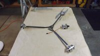
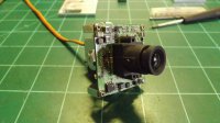
Hello all. I am presently designing and building a new Y6 I have named the Wraith. This project was started some time ago and am just now getting back into working on it. Do not expect immediate progress. I am retired and don't rush myself anymore. This is a project that is meant to be fun, not a time based burden.

I have been designing and building my own aircraft for many years (since 1975). I am a bit quirky and refuse to comply with the norm. You may note this in the following build. Being practical is not my way of doing things. One can only take so many years of being practical, before their designs become boring. With that in mind... this build is effective from an engineering perspective, yet is also artistic.

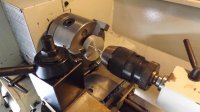
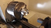
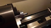
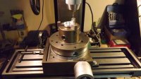
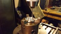
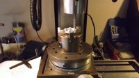
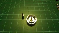
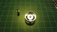
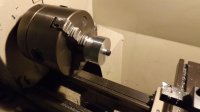
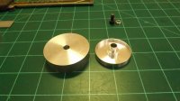
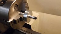
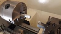
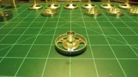
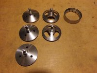
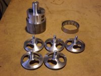
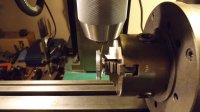
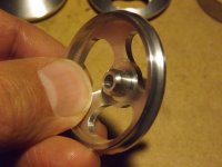
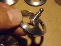
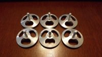
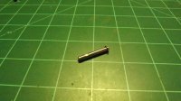
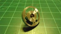
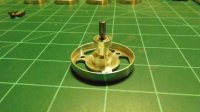
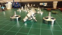
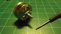
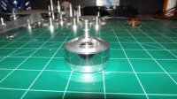
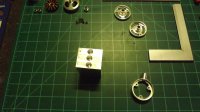
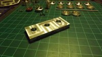
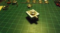
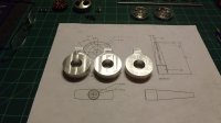
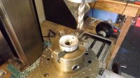
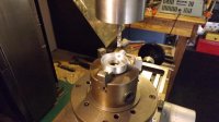
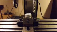
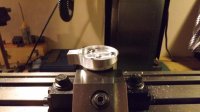
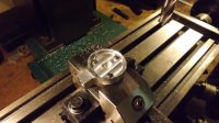
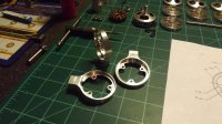
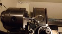
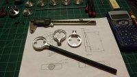
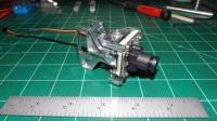
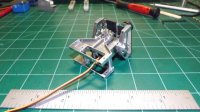
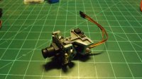
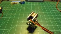
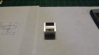
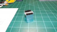
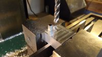
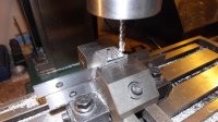
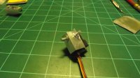
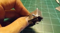
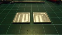
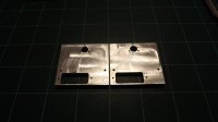
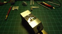
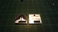
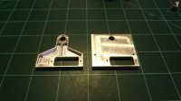
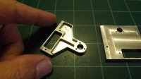
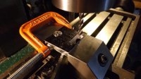
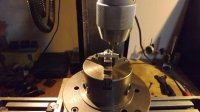
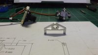
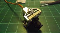
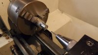
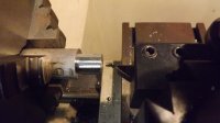
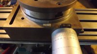
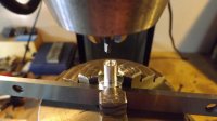
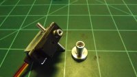
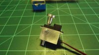
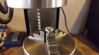
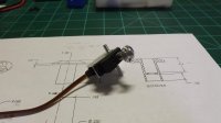
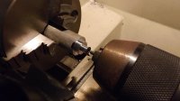
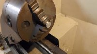
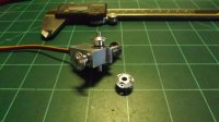
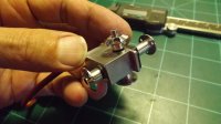
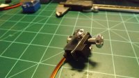
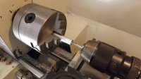
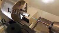
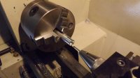
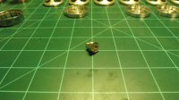
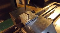
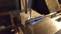
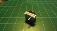
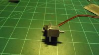
I started out with the motors. I needed six of them for the Y6 configuration. None of the manufactured motors meet my design criteria, so I set upon building my own. It is not that manufactured motors don't work well.. they are just fine. Their design and how they integrate into the rest of the model's design is the issue.

Here we go...
 

Thorn3

Member
The first step is to decide which material best suits the need. I decided to use 6061-T6 Aluminum. Easy to get, cost effective, easy to machine and has suitable mechanical characteristics.

The design started in Solid Works. From there, the individual drawings were printed out and the machining began. I do not intend this thread to be a tutorial in machining. I will however provide basic commentary as to what is shown in the pictures. I got carried away with machining at times, so I forgot to take some pictures.


View attachment 17215View attachment 17216View attachment 17217View attachment 17218

Started with some round stock. Blanks were machined for the motor bases, with a central hole. A fixture was then machined to hold the blanks (forgot to take pictures of that). Concentric parts are a must, so the fixture was machined and left in the lathe until all base parts were machined. For some reason.. two pictures are out of order. Hmm...
 

Attachments

  • B_1.jpg
    B_1.jpg
    138 KB · Views: 360
  • B_2.jpg
    B_2.jpg
    137.8 KB · Views: 264
  • B_3.jpg
    B_3.jpg
    119.5 KB · Views: 291
  • B_4.jpg
    B_4.jpg
    125.1 KB · Views: 286


Thorn3

Member

Attachments

  • B_7.jpg
    B_7.jpg
    141.1 KB · Views: 294
  • B_8.jpg
    B_8.jpg
    116.3 KB · Views: 256
  • B_9.jpg
    B_9.jpg
    124.4 KB · Views: 345
  • B_10.jpg
    B_10.jpg
    112.6 KB · Views: 281
  • B_11.jpg
    B_11.jpg
    124.4 KB · Views: 295

Thorn3

Member

Attachments

  • B_1.jpg
    B_1.jpg
    138 KB · Views: 270
  • B_2.jpg
    B_2.jpg
    137.8 KB · Views: 279
  • B_3.jpg
    B_3.jpg
    119.5 KB · Views: 248
  • B_4.jpg
    B_4.jpg
    125.1 KB · Views: 290
  • B_5.jpg
    B_5.jpg
    119.6 KB · Views: 265
  • BC_1.jpg
    BC_1.jpg
    140.3 KB · Views: 267
  • BC_2.jpg
    BC_2.jpg
    122.2 KB · Views: 274
  • BC_3.jpg
    BC_3.jpg
    114.2 KB · Views: 276
  • BC_4.jpg
    BC_4.jpg
    116.9 KB · Views: 272
  • BC_5.jpg
    BC_5.jpg
    128.9 KB · Views: 287
  • BC_6.jpg
    BC_6.jpg
    133.8 KB · Views: 287

Thorn3

Member
I am going to have to get used to how this forum deals with pictures. Not used to this method. Sorry if things come out strangely, as in the last post where there are pictures inline as well as thumbnails.. which I did not intend to do but can't seem to change.

Next up are the end bells. Machining them was a real chore. More time consuming than difficult. Once again, the use of fixtures is extremely important to insure concentric surfaces. Blanks are cut, then mounted to the fixture. The fixture remains in the lathe until all parts are finished. The parts are moved to the mill where they are slotted and drilled/tapped for the motor shaft set screws.


View attachment 17239View attachment 17240View attachment 17241View attachment 17242View attachment 17243View attachment 17244
 

Attachments

  • EB_1.jpg
    EB_1.jpg
    138.4 KB · Views: 249
  • EB_2.jpg
    EB_2.jpg
    133.5 KB · Views: 288
  • EB_3.jpg
    EB_3.jpg
    130.6 KB · Views: 241
  • EB_4.jpg
    EB_4.jpg
    129.7 KB · Views: 232
  • EB_5.jpg
    EB_5.jpg
    130.1 KB · Views: 204
  • EB_6.jpg
    EB_6.jpg
    143.2 KB · Views: 241

Thorn3

Member
Following are some pictures of the various motor parts in partial and full assembly. The motor shafts are hardened and polished tool steel. Clip slots were machined using the rotary table in the mill and a diamond slitting disk. Flats for the end bell set screws were machined the same way. Magnets, magnet rings and stators are waiting for final assembly. The stators are hand wound by me to a Kv of 750.

View attachment 17245View attachment 17247View attachment 17248View attachment 17249View attachment 17246View attachment 17250View attachment 17251
 

Attachments

  • MA_1.jpg
    MA_1.jpg
    125.2 KB · Views: 260
  • MA_2.jpg
    MA_2.jpg
    118.2 KB · Views: 241
  • MA_3.jpg
    MA_3.jpg
    131.6 KB · Views: 223
  • MA_4.jpg
    MA_4.jpg
    132.2 KB · Views: 264
  • MA_5.jpg
    MA_5.jpg
    134 KB · Views: 246
  • MA_6.jpg
    MA_6.jpg
    134 KB · Views: 266
  • MA_7.jpg
    MA_7.jpg
    117.3 KB · Views: 259

Thorn3

Member
Next up are the motor mounts. These started out as rectangular bar stock. Shown in one of the pictures is an older motor mount design. Ignore that. For these parts a fixture is used to hold the stock in the rotary table of the mill. The one mount shown in the fixture is also one of the older designs, but it is the only picture I have, showing the fixture holding a piece of stock.


View attachment 17253View attachment 17252View attachment 17254View attachment 17255View attachment 17256View attachment 17257
 

Attachments

  • MM_1.jpg
    MM_1.jpg
    136.1 KB · Views: 236
  • MM_2.jpg
    MM_2.jpg
    141.1 KB · Views: 229
  • MM_3.jpg
    MM_3.jpg
    138.1 KB · Views: 237
  • MM_4.jpg
    MM_4.jpg
    140 KB · Views: 228
  • MM_5.jpg
    MM_5.jpg
    143.9 KB · Views: 225
  • MM_6.jpg
    MM_6.jpg
    130.2 KB · Views: 266

Thorn3

Member
The second fixture is designed to hold a motor mount in the mill, to machine the walls to a taper. The fixture remains where it is through the machining of all three motor mounts, to insure they are all the same. A finished mount is shown fitted to one of the three CF tubes. These tubes are thinner than what most people use. They are also different in that they are made with linear fiber inside, wrapped in braid. They are strong enough to support my weight. One picture shows a motor mount in the lathe. This is just to round off where the CF limb enters the mount. The final blending was done with a series of hand files. All mounts were then polished.


View attachment 17259View attachment 17258View attachment 17260View attachment 17261View attachment 17262View attachment 17263
 

Attachments

  • MM_7.jpg
    MM_7.jpg
    121.4 KB · Views: 245
  • MM_8.jpg
    MM_8.jpg
    120.3 KB · Views: 259
  • MM_9.jpg
    MM_9.jpg
    142.3 KB · Views: 239
  • MM_10.jpg
    MM_10.jpg
    141.1 KB · Views: 246
  • MM_11.jpg
    MM_11.jpg
    143.6 KB · Views: 250
  • MM_12.jpg
    MM_12.jpg
    134.9 KB · Views: 263

Thorn3

Member
I fly FPV. With this in mind, my setup will have a starlight camera for flying in various light conditions, including at night. I also like to be able to look around in real time, so a gimbals assembly was designed. Here are pictures of it so far. I will post pictures of parts being machined next.

View attachment 17265View attachment 17266View attachment 17267View attachment 17268View attachment 17269View attachment 17270

The second (pan) servo has been installed. Now a connecting rod will be machined to finish off the basic assembly.
 

Attachments

  • GA_1.jpeg
    GA_1.jpeg
    57.7 KB · Views: 424
  • GA_2.jpg
    GA_2.jpg
    142.4 KB · Views: 309
  • GA_3.jpeg
    GA_3.jpeg
    61.6 KB · Views: 423
  • GA_4.jpeg
    GA_4.jpeg
    60.5 KB · Views: 343
  • GA_5.jpg
    GA_5.jpg
    141.5 KB · Views: 347
  • GA_6.jpg
    GA_6.jpg
    142.1 KB · Views: 163

Thorn3

Member

Attachments

  • SH_1.jpg
    SH_1.jpg
    76.4 KB · Views: 176
  • SH_2.jpg
    SH_2.jpg
    128.3 KB · Views: 147
  • SH_3.jpg
    SH_3.jpg
    141.6 KB · Views: 166
  • SH_4.jpg
    SH_4.jpg
    145 KB · Views: 187
  • SH_5.jpg
    SH_5.jpg
    135.8 KB · Views: 153
  • SH_6.jpg
    SH_6.jpg
    117.5 KB · Views: 136
  • SH_7.jpg
    SH_7.jpg
    129.9 KB · Views: 149
Last edited by a moderator:


Thorn3

Member

Attachments

  • PB_1.jpg
    PB_1.jpg
    110.8 KB · Views: 137
  • PB_2.jpg
    PB_2.jpg
    78.8 KB · Views: 157
  • PB_3.jpg
    PB_3.jpg
    140.6 KB · Views: 158
  • PB_4.jpg
    PB_4.jpg
    115.3 KB · Views: 157
  • PB_5.jpg
    PB_5.jpg
    120.3 KB · Views: 139
  • PB_6.jpg
    PB_6.jpg
    117.6 KB · Views: 150

Thorn3

Member

Attachments

  • TB_1.jpg
    TB_1.jpg
    139.9 KB · Views: 167
  • TB_2.jpg
    TB_2.jpg
    135.7 KB · Views: 145
  • TB_3.jpg
    TB_3.jpg
    92.1 KB · Views: 134
  • TB_4.jpg
    TB_4.jpg
    131.8 KB · Views: 147
  • TB_5.jpg
    TB_5.jpg
    142 KB · Views: 154

Thorn3

Member
Bearings are needed in the gimbals assembly. Igus brand sleeve bearings were chosen due to their light weight and ability to handle the ingestion of debris. Ball bearings would have been a good option as well, but at a cost of weight. All four bearings were machined from round stock. It starts out in the lathe, moves to the mill and back to the lathe to finish. The first bearing is really a coupling to couple the servo output shaft to the tilt axis. It is the longest of the bearings and requires that a spline be cut into it.


View attachment 17292View attachment 17293View attachment 17294View attachment 17295View attachment 17296View attachment 17297View attachment 17298View attachment 17299
 

Attachments

  • BP_1.jpg
    BP_1.jpg
    121.2 KB · Views: 150
  • BP_2.jpg
    BP_2.jpg
    108.8 KB · Views: 168
  • BP_3.jpg
    BP_3.jpg
    137.1 KB · Views: 183
  • BP_4.jpg
    BP_4.jpg
    126.7 KB · Views: 185
  • BP_6.jpg
    BP_6.jpg
    131.1 KB · Views: 148
  • BP_7.jpg
    BP_7.jpg
    135 KB · Views: 164
  • BP_8.jpg
    BP_8.jpg
    120 KB · Views: 158
  • BP_9.jpg
    BP_9.jpg
    99.6 KB · Views: 169


SoCal Blur

Member
Impressive! I have a few questions. First, what is it about commercially available motors that did not meet your requirements? Second, How long did it take you to fabricate the motors? And finally, how did you fasten the two motors to the mount? It looks like you actually have to assemble the motors after they are mounted...but that's just a guess from looking at the pictures.
 

Thorn3

Member
SoCal Blur: Thanks. My motor requirements are much like a person who builds their own sports car. The engines don't only perform at their peak for a given application, but they are also a work of art inside and out. Form and function follow the overall design. Purchased motors are not designed for a particular model. They can't be, as they don't know what the motors will be used in or for. My motors are designed to be part of the overall design, down to the parts and materials used and processes. Manufactured motors that meet my specs would be prohibitively expensive. In the end, it is fun to develop my own motors. I get exactly what I want, for far less than a manufactured motor. My designs don't have to revolve around motors. I can design the motor to fit my needs, look the way I want them too and seamlessly integrate into my designs. Can't get that from a manufactured motor. If I were to describe all the details as to why manufactured motors are not for me, it would look like I am ripping on them. I don't want to give that impression. Manufactured motors enable thousands of people to build models and have fun with them at a reasonable cost. To me, building my own motors is simply part of the fun of building the model.

I really have no idea how long it took me to machine the parts for the motors. I wasn't concerned with that. Just doing it was fun. I gave up clock watching when I retired.

In order to maintain a 'single motor' look per limb, the method of mounting them had to be changed from the norm. Both motors per limb are built as 'one' motor. There are both technical and artistic reasons for this. Better airflow across both motors, no need for added coverings to give a single motor look... etc. It is all just part of the overall design, using the least amount of material. These motors are unique to this build. Another build will get its own motors for the same reasons.

To me, it is not enough to fly. Creating the model is just as fun.


SoCal Blur

Member
SoCal Blur: Thanks. My motor requirements are much like a person who builds their own sports car. The engines don't only perform at their peak for a given application, but they are also a work of art inside and out. Form and function follow the overall design. Purchased motors are not designed for a particular model. They can't be, as they don't know what the motors will be used in or for. My motors are designed to be part of the overall design, down to the parts and materials used and processes. Manufactured motors that meet my specs would be prohibitively expensive. In the end, it is fun to develop my own motors. I get exactly what I want, for far less than a manufactured motor. My designs don't have to revolve around motors. I can design the motor to fit my needs, look the way I want them too and seamlessly integrate into my designs. Can't get that from a manufactured motor. If I were to describe all the details as to why manufactured motors are not for me, it would look like I am ripping on them. I don't want to give that impression. Manufactured motors enable thousands of people to build models and have fun with them at a reasonable cost. To me, building my own motors is simply part of the fun of building the model.

I really have no idea how long it took me to machine the parts for the motors. I wasn't concerned with that. Just doing it was fun. I gave up clock watching when I retired.

In order to maintain a 'single motor' look per limb, the method of mounting them had to be changed from the norm. Both motors per limb are built as 'one' motor. There are both technical and artistic reasons for this. Better airflow across both motors, no need for added coverings to give a single motor look... etc. It is all just part of the overall design, using the least amount of material. These motors are unique to this build. Another build will get its own motors for the same reasons.

To me, it is not enough to fly. Creating the model is just as fun.

Thanks for the response. I take it prior to your retirement, you were a machinist? I understand the desire to create every aspect of your model. I suppose if I had the equipment (and the skill set) I would do the same. Great work!
 

Top