KDE Direct
KDE Direct, LLC.
Hey Everyone,
Development of the thrust and efficiency data for each sUAS Brushless Motor is a critical design aspect our our Research and Development, and we make sure to post this for each motor edition on our website: http://www.kdedirect.com/XFMRBrushlessMotors.html.
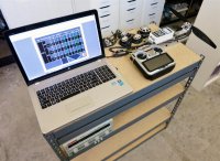
We receive various e-mails about how our data is obtained, so we felt it's best to show you our custom-dynamometer and the critical features installed for accuracy. We recently completed our new Dyno design, with laboratory-grade equipment and custom-CNC machined components, so that we can provide the most accurate data possible to match real-life flight conditions. The entire system was qualified and calibrated at a local laboratory, and then put into use at our facility. Real-life flight conditions vary greatly, depending on setup and environmental affects (humidity, altitude, temperature, etc.), as well as propeller designs, which vary greatly between brands and quality-levels.
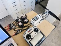
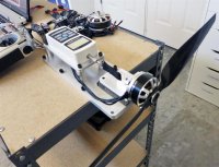
All the data is collected on a propeller-test stand, custom build to our needs. The components are:
Power Supply: VOLTEQ Power Supply HY5050EX 50V/50A (custom code updated to 75A output capability)
Force Gauge: MARK-10 Advanced Digital Force Gauge Series 4 (25kg maximum, 10g accuracy)
Linear Roller Slide: Del-Tron RS2-2
Electronic Speed Controller: KDE Direct XF UAS 75HV+ Electronic Speed Controller
Transmitter and Receiver: Futaba 18MZ, R6202SBW
Environment Conditions: 70F, 35% Humidity, 300ft Elevation Altitude
The fixture was designed and built at our KDE Direct facility in Washington, USA. The system is capable of testing all motors, from the KDE1806XF series on 7.4V up to the KDE7215XF-135 at 50.4V, so full capability and high-accuracy for sUAS development. We not only test the KDE Direct products, but also our competitors, to make sure we are always leading the market in the latest technology and performance capabilities. Our goal is to provide the best data possible and there's always ways to argue data or the methods for collection, but here's our system and any deviations from this will provide variable results, depending on the accuracy of your own system and environmental effects.


Development of the thrust and efficiency data for each sUAS Brushless Motor is a critical design aspect our our Research and Development, and we make sure to post this for each motor edition on our website: http://www.kdedirect.com/XFMRBrushlessMotors.html.
We receive various e-mails about how our data is obtained, so we felt it's best to show you our custom-dynamometer and the critical features installed for accuracy. We recently completed our new Dyno design, with laboratory-grade equipment and custom-CNC machined components, so that we can provide the most accurate data possible to match real-life flight conditions. The entire system was qualified and calibrated at a local laboratory, and then put into use at our facility. Real-life flight conditions vary greatly, depending on setup and environmental affects (humidity, altitude, temperature, etc.), as well as propeller designs, which vary greatly between brands and quality-levels.
All the data is collected on a propeller-test stand, custom build to our needs. The components are:
Power Supply: VOLTEQ Power Supply HY5050EX 50V/50A (custom code updated to 75A output capability)
Force Gauge: MARK-10 Advanced Digital Force Gauge Series 4 (25kg maximum, 10g accuracy)
Linear Roller Slide: Del-Tron RS2-2
Electronic Speed Controller: KDE Direct XF UAS 75HV+ Electronic Speed Controller
Transmitter and Receiver: Futaba 18MZ, R6202SBW
Environment Conditions: 70F, 35% Humidity, 300ft Elevation Altitude
The fixture was designed and built at our KDE Direct facility in Washington, USA. The system is capable of testing all motors, from the KDE1806XF series on 7.4V up to the KDE7215XF-135 at 50.4V, so full capability and high-accuracy for sUAS development. We not only test the KDE Direct products, but also our competitors, to make sure we are always leading the market in the latest technology and performance capabilities. Our goal is to provide the best data possible and there's always ways to argue data or the methods for collection, but here's our system and any deviations from this will provide variable results, depending on the accuracy of your own system and environmental effects.
")