iSeismometer use for Motor balancing

When the IPhone is laid flat on it's back on an MR arm for motor vibration monitoring, the "z" axis aligns, i.e., is in parallel with the motor rotor.
It would seem that this up/down vibration would be eliminated once the prop is installed and pulling in the up direction only.
So does this mean one should ignore the "z" axis vibration data when balancing each motor?

Here are some vibration samples from my last attempt to balance some of the motors.View attachment 11172View attachment 11173View attachment 11174:dejection:
 

Attachments

  • 2013-04-16 21.49.46.jpg
    2013-04-16 21.49.46.jpg
    15.1 KB · Views: 321
  • 2013-04-16 21.36.29.jpg
    2013-04-16 21.36.29.jpg
    14.3 KB · Views: 373
  • 2013-04-16 21.31.34.jpg
    2013-04-16 21.31.34.jpg
    14.4 KB · Views: 336

Bison52

Member
I'm interested in this also. In my first rudimentary attempts at motor balancing, the Z axis usually shows the worst vibration and responds least to balancing attempts.
 

Remember that the hi-pass filtering determines whether or not the earth's gravitional force is entered into the data trending such that the Z axis will show a higher magnitude than the others when g-force is also sensed.
But switching g-force off reduces the iSeismometer sensitivity such that the tool is not nearly as useful for motor balancing.
Reference: see the App tutorial....on the internet.

I'm interested in this also. In my first rudimentary attempts at motor balancing, the Z axis usually shows the worst vibration and responds least to balancing attempts.
 

Here is some new information from a Mechanical Engineer who has over 12 years experience specializing in motor vibration analysis......I will resubmit new data and provide additional details to him in the hopes he can provide more complete data for us.

"regarding your motor balancing..... the plots that you sent me are time waveform plots. i can't really tell the time scale of the plots though. in the iPhone app is it possible to cover from time waveform to FFT (frequency spectrum)? that way i can tell the running speed of the motor or maybe you know the running speed? 1800 rpm? anyway...... unbalance shows up in a frequency spectrum at 1x running speed. normally to accurate balance something you need to have a phase reference in order to tell where you "heavy" spot is on you 1x sinusoidal waveform but maybe there is an iphone app for that or you can also do it by trial and error with small trial weights. if you can convert the time waveform to FFT i might be able to help more. the z axis typically is never affected by balancing."


ChrisViperM

Active Member
Here is some great back-ground info on vibrations: http://www.irc.wisc.edu/file.php?id=229

Theoretically (assuming one got enough time and patience) you should first balance the motor without props.....than balance the props with a balancer as close as possible. After that mount the props and measure again.....After doing that myself and some playing arround I found out that - if you have to add weight to the props to balance them - it not only depends on how much weight (tape, glue, nail polish.....) you take, it also depends where you add that weight on the prop. If you take a prop and think a line along it's
blades and than think another line in 90° through the center of the hub, you get 4 "sectors" A,B,C and D....look at the picture:

View attachment 11188

Since the prop is a 3-dimensional structure, A and B have a different weight. A should be equally heavy (counterbalanced) with C, and B should be equally heavy D. If you balance your props horizontally (blade tips left and right) you normally stick some weight on the lighter side until left and right is in balance....and think "ok...now it's balanced....". If you turn the props in a horizontal position (blade tips up and down) one side might tend to fall to the left or to the right....and than the nonsens with "hub balancing" starts. People glue velcro tape and all sorts of rubbish to the hub and wonder how much weight they need to see any affect. In most cases the hub is not out of balance (sometimes it is) but the weight distribution on all 4 sectors is somewhere out of balance, and even sticking weight during horizontal balancing might add to that. To check the hub you just need a cheap digital caliper to measure the hub. It would have to be really out of measurement to have an affect on your vertical balance. Even if the prop is horizontally perfectly in balance out of the box, you might have to stick equal weights on both blades (in different locations on the blade) to get it vertically balanced as well. As sad as it is, but I have not found a way other than trial and error....and it's a freaking pain in the butt.

Another big factor is flex in the props and blade tracking....I have settled for Xoar wooden props on all my rigs.


Chris
 

Attachments

  • Xoar-PJN-Electric-Props.jpg
    Xoar-PJN-Electric-Props.jpg
    26.7 KB · Views: 347

Additional information from the Mechanical Engineer who has made a career in balancing rotating equipment......

"in order to balance the motors you'll have to have them running at constant speed from test to test. you can find a procedure online if you google "balancing without phase measurement". you'll need polar plot paper (which you can download), a compass & small trial weights. i'll see if i can find a decent procedure online but i'm sure you'll be able to find something. you'll have to run the motors 3-4 times with trial weights at 0 deg, 120, 240 measuring the vibration amplitude at 1x running speed. important that the speed is constant from test to test. it's been about 20 years since i've actually done this in the field but it does work........ of course what you're dealing with are very small motors so it might be more difficult."

My additional comments:
Seems that this method requires a single axis vibration sensor. IPhone has such an app.
It could be attached to the non-spinning base of the brushless motor which is where the bearing is located......
https://docs.google.com/folder/d/0B_VSHTb5vQOyNzUyY2E4NmYtODJjMC00MjFmLWI2ZjktZWZjMTVlOWU4ZTc1/edit
http://reliabilityweb.com/index.php/maintenance_tips/balancing_without_phase/

http://www.vibronurse.com/NoPhaseBalance.html


The so-called running speed in this case can be any consistent speed between hover and full speed.
For high speed balancing and for the purpose of maintaining a consistently constant speed for these balance tests, the full speed seems most appropriate.

PS: Anyone know where to buy a weigh scale that can weigh in micrograms?
 
Last edited by a moderator:


DucktileMedia

Drone Enthusiast
interesting but I would not do this at all. This is why.... you are entirely relying on the accuracy of the threads to make that work. And I can even see in this video the wobble is so much that I guarantee you the bell housing is not that off, its the tube making it show that way. Having machined parts for many many years I have actually come across this issue before. The reason the threads can be ever so slightly off is because the centering of the prop is reliant on the shaft of the prop adapter, not the threads. The threads only allow the nut to grip the prop. In short, I would NOT rely on this method. However, it does present an interesting idea of making something that is totally accurate and self centering, like a cone. But keep in mind if anything is so much as a thousandth of an inch off it will yield inaccurate readings in balance. Still think the conventional method of spinning on the actual motor shaft is ideal since that is where it will be when you are done with the balance anyways.
 

Zbip57

New Member
you are entirely relying on the accuracy of the threads to make that work.
Before removing or disassembling the motors I screwed the tube onto the top of each motor shaft and gave them a spin. The tube had no wobble to it at all. Stood straight up.

I can even see in this video the wobble is so much that I guarantee you the bell housing is not that off, its the tube making it show that way.
One of the four motors was perfect as-is, needing no balancing at all. This motor was way out though. True, you can clearly see in this video how much the bell housing wobbles. If that was caused by the tube not being screwed on square then you should see a similar amount of wobble at the joint between the tube and the motor shaft. Hold your screen cursor on the video at the edge of the tube (not the keyed portion of the motor shaft, eh) and watch to see how little it moves up and down.

This motor's bell housing is way out of whack.

In short, I would NOT rely on this method.
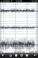
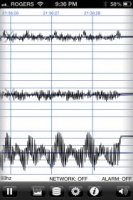
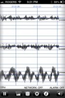
I don't own an iPhone, and have no access to the iSeismometer app. I knew for certain that the motors were out of balance because, with the props removed, the Phantom would dance the jitterbug all across the table when the motors were run.

I opened up the shell and disconnected the ESCs three at a time from the NAZA controller so I could run each motor individually. Then I balanced them by trial and error, relying just on the sound and feel for whether the vibration improved or got worse. That helped, but it wasn't perfect. Running all four motors together again would be smooth at half throttle, but the Phantom still buzzed around the table at full throttle.

Doing the balancing this way, with the tube on a Du-Bro balancer, for sure it's only a static balance -- not dynamic. But, there's no guesswork involved as to where to stick the balancing tape. It's just a question of how much tape to apply.

I wish I had taken a video of the Phantom buzzing around on the table before I balanced the motors. But, after balancing, the difference was amazing.

In the last shot where I'm running the motors, the tube is lying loose on the table, just to the left of my hands. There isn't even enough vibration left to get that tube rolling on the table.

It's maybe not a perfect method, but it's a whole lot simpler and cheaper than buying an iPhone.
 

HI Zbip57, This method I think is great, I do not have the phantom but the F550 with DJI 920 motors (similar problem). I had also thought of balancing the bells with my DuBro but could not cum up with anything off the shelf to extend the prop shaft end so it would fit the dubro. I could not believe in seeing your video how far the bell was running out of true. If one wanted to be really pedantic about checking the thread / center punch tube accuracy, it could be done with a dial indicator to see how far it was running out of true. Compared to the bell, a few thou on the center punch tube would be nothing. Thank you very much for going to the trouble of presenting another alternative to balancing brushless motors.
Regards - bruce
 

ChrisViperM

Active Member
PS: Anyone know where to buy a weigh scale that can weigh in micrograms?

This would be a reasonable priced scale:


Here is some DIY approach:


One project for dark and long winter nights:
http://sci-toys.com/scitoys/scitoys/mathematics/microgram_balance/balance.html


I remember from my RC-cars time that when it came to set-up the cars (toe-in or toe-ot, camber, tire truing....) for optimum performance, everybody had a different approach and different tools, ranging from simple DIY things to highly "sientific"....then a company called HUDY started up with tools and devices especially made to simplify the set-up procedure: http://www.hudy.net/flash_stuff/all_in/index.htm, and they are very sucessful for many years now. Chinese (obviously) tried to copy, but failed so far because of the high quality of HUDY stuff. With Multirotors we are in a very similar position (and a dayily growing market), and I would assume that if someone would come up with special tools tailored for our specific needs (especially balancing) it would be a great success.

Chris
 
Last edited by a moderator:

Top