How Do You Avoid Sparking During Battery Connection

gtranquilla

RadioActive
What are you flying? If it's big (like 800mm+) switch to what DJI is using. Honestly i took an afternoon to change everything to a AS150/XT150 setup... and since then... just brilliant!

Just make sure to heat up those large brass connectors enough to get a good/solid solder! I use a butane soldering iron, with the torch tip for those. Works great, $20 at Radio Shack.

Also make sure you connect the opposite barrel end to the anti-sparking terminal. It provides heat dispersion so that the ring insulator on the resistor tip does not melt.


MombasaFlash

Heli's & Tele's bloke
...try to put your connectors together so that the positive poles are touching before you bring the negative poles together. by doing this you're forcing the electricity to run all of the way through the capacitors and through the electronics before the spark occurs so it will be greatly reduced.

For anyone who is concerned about being concerned about battery start-up sparks, i lived with it until one of my connectors de-soldered in flight as a result of spark corrosion with consequent massive resistance and heat build up. Fortunately it was a test flight and it fell out of the sky for a total of about eight inches with no harm done. It was hovering .... and then it wasn't.

After trying various anti-spark devices I now use a 'throwaway' connector cable. As all airframes are fitted with dual battery connectors they are powered up initially using the 'throwaway cable' on the first battery, then the second battery is connected, then the throwaway disconnected and the first battery connected directly.

A bit of a carry on but all the important connectors stay pristine and easy to use. I also disconnect in the reverse order, as I have noticed that sparking can also occur with a clumsy disconnect. The result is that there has been no massive battery connector change or outlay. Cheaper and simpler.

As for the 'throwaway', the extra burnt out connector pair half way down one line is replaced easily every so often. Rather than waste my normal 6mm bullets, I use whatever connectors that come supplied with stuff that I don't normally use instead of throwing them away.

And by the way, I have two 'throwaway cables'. One with the break on the positive line and one on the negative line. They both spark equally ferociously, so Bart's theory doesn't work for me.
 
Last edited by a moderator:

Hi, Barts theory would not work for anyone, for electrons to flow you need a circuit, one connection + or - does not constitute a circuit therefore no flow until the circuit is closed then bang the spark and surge of electrons.
regards - bruce
PS there are now plenty of anti-spark connectors available in the market place.
 

SJBrit

Member
OK, just ordered the AS150/XT150 - hopefully I'll have better luck with them. I think I'll just make a parallel pigtail to the XT90s so I don't have to change every battery over.
 

RotorJockey

Member
Hey Guys

I do electronics and want to share some theory (and practice) with you.

The capacitors in the ESCs and any other circuitry are at the discharge voltage (i.e. zero volts). When a supply is connected, the voltage difference and the resulting current (Amps) causes the spark (Amps = Volts ÷ Resistance. No resistance, maximum Amps). The capacitors want to charge to the applied voltage immediately. This causes a tiny hole in the plating, raising the connection resistance with each spark. To stop this economically, buy a 5 to 10 ohm (measure of resistance) 1 watt resistor and insert it in a "throw-away" lead on the battery to be used, or another of similar 'S' rating. This will charge the capacitors and by (as quickly as possible) replacing this lead with your normal 'feed' cable, the voltages are similar and (ideally) no spark will appear. So also allowing the + and - leads from the ESC to touch each other, discharges the capacitors, causing even a heavier spark (a capacitor has no current limiting.
The 'suppresser' connectors have a split barrel with a resistor between them, first making contact through the resistor and then shorting out the resistor to supply full capability.
Hope this helps
 

RotorJockey

Member
BalanceAnyLayersLightlySir. Electro-static-voltage (EHT) does not feature in this problem - it is completely another aspect of damage to electronic components.

Low tension spark is caused by the relatively (momentary) high resistance while completing the circuit, and the extreme current flow when this contact is finally made. Where do you think an arc welder gets its spark from?? Low voltage, high current, almost no resistance - that can cause damage in the wrong hands! Better keep your hand in your pockets, sir.
 

SJBrit

Member
LOVE the AS150/XT150 setup - really nice connectors. Absolutely zero spark, very firm connection and easy to disconnect. Perfect! I made up a Y harness so I now connect my two batteries in parallel via XT90s which run into the AS/XT150s. That way I just have a single connection to make for power on. I'm finally happy with my power setup! third time's a charm....
 

Palin

Member
LOVE the AS150/XT150 setup - really nice connectors. Absolutely zero spark, very firm connection and easy to disconnect. Perfect! I made up a Y harness so I now connect my two batteries in parallel via XT90s which run into the AS/XT150s. That way I just have a single connection to make for power on. I'm finally happy with my power setup! third time's a charm....

I have the AS150/XT150 connectors on my S900 with a 16,000mAh battery and I get a spark on the positive lead (after connecting the negative lead first). I kind of expected no spark with it being an anti-spark connector. Am I missing something here? Is the current draw just too great for these connectors not to spark?
 

SJBrit

Member
I have the AS150/XT150 connectors on my S900 with a 16,000mAh battery and I get a spark on the positive lead (after connecting the negative lead first). I kind of expected no spark with it being an anti-spark connector. Am I missing something here? Is the current draw just too great for these connectors not to spark?

I'm not really sure. What's your setup? In terms of current draw at startup, that should simply depend on voltage and the components you're powering up. I'm running a quad on 6S so you have 50% more ESCs than me - maybe that's a factor? Perhaps someone with more props than me can comment.
 

Mojave

Member
I have the AS150/XT150 connectors on my S900 with a 16,000mAh battery and I get a spark on the positive lead (after connecting the negative lead first). I kind of expected no spark with it being an anti-spark connector. Am I missing something here? Is the current draw just too great for these connectors not to spark?
[MENTION=16367]Palin[/MENTION]: from post #8 above positive first:

guys,

try to put your connectors together so that the positive poles are touching before you bring the negative poles together. by doing this you're forcing the electricity to run all of the way through the capacitors and through the electronics before the spark occurs so it will be greatly reduced.

bart
 

Palin

Member
It's fully loaded with 3 cameras, iosd ii, gh4, z15, 2xVTs. I'm not convinced about connecting the +version first. Surely the path is irrelevant. It's the point of contact which is still going to have the same current flowing through. I tried it once, but it just moves the spark to the -ve terminal. I was a microelectronics engineer for 10 years, although that was 15 years ago so I'll accept I'm rusty.
 

SJBrit

Member
But that's the exact opposite from the directions that come with the connectors, which is how I'm connecting them (with zero spark). To be honest I'm not sure about this positive first thing - nothing happens in an electrical circuit until there is a closed path for electron flow, and the instant there is such a path then they go ahead and flow - it doesn't mater where in the circuit the final path is connected. The spark is simply caused by the high level of current being drawn which will actually jump a small air gap, hence the spark.

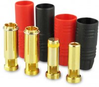
You MUST connect anti-spark connectors in the right order or you will defeat them: they have a two-stage positive connection: the first stage through a small resistor to reduce the current flow on initial connection, and then when you push the bullets together further the main, secondary connection is mated which is your current flow during operation (and gets over the "what if the resistor fails?" loss of power issue). If you connect positive first the the negative will spark. Check out the yellow band on the positive male bullet in the picture. That separates the anti-spark tip from the main current carrying connection,

attachment.php

[MENTION=16367]Palin[/MENTION] - I wonder if you are just pushing the bullets together too fast? Try slowly pushing the positive together so that the tip can do it's job before the main connection is made. That's really all I can think of. Or perhaps the resistor is dead and it's just not functioning as a spark-arrestor. You should be able to check that by checking the resistance between the tip and the main bullet body. I'll measure mine to let you know what it should be.
 

Attachments

  • YUKIKING-AS150-1-x-Set-Anti-Spark-600214_b_0.JPG
    YUKIKING-AS150-1-x-Set-Anti-Spark-600214_b_0.JPG
    83.8 KB · Views: 223

SJBrit

Member
OK, 5.8 ohms between the tip and the main body. If you are seeing either zero or infinity then you will get a spark (zero - resistor has failed to a short, infinity - resistor has failed to an open circuit). You might also be able to see discoloring where the spark has been occurring. If the resistor is good and you see discoloration on the main body, then I suspect you are pushing the connectors together too fast. If on the tip then I have no idea what's going on, other than perhaps it can't handle as much power as you are pulling.
 

Palin

Member
Thanks [MENTION=15190]SJBrit[/MENTION], that's the point I was making. Appreciate u checking the resistance for me. It'll be a couple of days before I can check, but I certainly will and also try the slow connection approach.


scotth

Member
I have had sparking and burned connectors from day one on my S1000 with these connectors. I had ordered a spare and just now checked the resistance of the OEM connector and the new one and sure enough, the original is open from ring to tip. The new one shows about 6 ohms. Thanks for the heads up.
 
Last edited by a moderator:

Palin

Member
I have had sparking and burned connectors from day on on my S1000 with these connectors. I ordered a spare and just now checked the resistance of the OEM connector and the new one and sure enough, the original is open from ring to tip. The new one shows about 6 ohms. Thanks for the heads up.

I haven't measured the one on my S900, but I just checked my 2 spare connectors and they're reading circa 8 ohms (bound to be a bit of variation in the tolerances).
 

Top