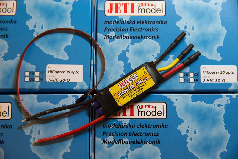
Product Review ** JETI HiCopter 30A Opto ESC


gtranquilla

RadioActive
Excellent to see this all done "the right way" with quality freq generator, Oscilloscope etc.
I have a couple of comments/questions though:
1) Zooming in on the leading edge of one phase output, can you see any volt spike issues or has newer ESC circuit design eliminated that issue?
V-spikes can punch holes in the insulation on the first few windings of the motor coils leading ultimately towards winding short circuits over time.
Inverter rated motors use heavier/thicker insulation on the first few windings to help to increase motor life.

2) IEEE-519 Harmonic issues...... High frequencies between ESC and motors tend to turn the ESCs into small EMI/RF transmitters such that EMI can migrate back on to the power supply side, e.g., the PDB.
If one motor/esc misbehaves so as to generate more emi on the power leads, then all remaining ESCs would also be adversely affected. Harmonic issues start at the 5th harmonic. Are the caps on each ESC enough to handle these risks?


JETI HiCopter 30A Opto ESC Review

PART 1: OVERVIEW

JETI_zpsabc8facc.jpg


In the simplest sense, what we want to know most about an ESC is whether it works. So let's deal with this most essential question first: Yes, these HiCopter ESCs work just fine. I plugged them into a test quad with a Naza v2 flight controller. In light wind everything worked as expected with stock gains and no issues whatsoever.

Feel free to skip the video. There is truly nothing unusual to see here.

https://vimeo.com/96621915

The ESCs are delivered in a nice box. The motor connections are the usual bullets, but with the handy flexibility of extension wires (as opposed to being soldered to the board). The power and signal wires are a comfortable length.

There are no settings for the HiCopter ESCs. There is no throttle calibration, no programming card, and no USB interface. Generally speaking, this is probably a good thing.


The 500Hz frequency response is nice, but typical (more on this later). More impressive is the optical separation of the signal side from the power delivery side of the ESC. ESCs tend to be marketed as “opto” when they do not output 5 volt power over the servo connection. But some “opto” ESCs produce their own 5 volt operating power from the main ESC power connection. This sounds reasonable until we realize that the connection can introduce noise back into the servo wires. You can’t just clip the voltage wire to fix the problem in many cases because the noise will be present on the ground wire too.

Thankfully, the HiCopters are true “opto” ESCs. They provide no power on the servo connection cable and require a 5v supply to operate. Most flight controllers will provide the needed power over the servo cable with no issues. This is a very nice feature, and is not to be assumed in just any “opto” ESC.

One almost ritualistic task — throttle setting — is noticeably absent. You shouldn’t care about this. Most flyers set ESC throttle endpoints incorrectly anyway, at least judging by what I see online. The basic problem is that people tend to set throttle with a direct connection to the radio receiver. Some even build special cables for this. In actual use, however, the flight controller is talking to the ESC, and will have its own independent throttle endpoints that need not match those of the radio. If your motors start when you want them to start, stop when you want them to stop, and deliver enough peak power to satisfy your flight demands then the throttle setting is just fine. The flip side of this is that you can’t really screw things up too badly by setting throttle endpoints incorrectly.

Many other ESC options are either anachronistic or confusing to the user. Sure, lipo destruction is bad, but worse is my copter falling out of the sky because the ESC is deciding to save the battery. It’s nice that the HiCopters have voltage cut-off preset to “the lowest possible level”. I would prefer no voltage cutoff at all. Admittedly, low-level cutoffs are often so low as to be effectively irrelevant, assuming the ESC correctly identifies the cell count of your lipos. The big worry is that the ESC misinterprets your lipo cell count and then cuts power inappropriately. In practice, I can’t get this to happen so I suppose it’s not worth worrying about. Nonetheless, it would be nice to see an ESC maker eliminate this feature altogether.

In sum, on specs and in actual use these are high-quality ESCs that perform well. But that’s no reason not to drill down on performance details. With modern multirotor flight controllers, the user only interacts with the ESC indirectly, and it is almost impossible for the typical flyer to separate the flight controller from the performance of the ESCs. This review attempts to get at a few direct measurements of ESC performance. Please comment on whether you find this helpful and if any additional metrics would be desirable.

This review continues below with a section on how ESCs function (using the HiCopter ESC as example), followed by analysis of the HiCopter ESC as compared to a T-Motor 30A Pro Opto ESC and a Castle Creations Phoenix Talon 35A ESC.
 
Last edited by a moderator:

econfly

Member
Excellent to see this all done "the right way" with quality freq generator, Oscilloscope etc.
I have a couple of comments/questions though:
1) Zooming in on the leading edge of one phase output, can you see any volt spike issues or has newer ESC circuit design eliminated that issue?
V-spikes can punch holes in the insulation on the first few windings of the motor coils leading ultimately towards winding short circuits over time.
Inverter rated motors use heavier/thicker insulation on the first few windings to help to increase motor life.

2) IEEE-519 Harmonic issues...... High frequencies between ESC and motors tend to turn the ESCs into small EMI/RF transmitters that can migrate back on to the supply side, e.g., the PDB.
If one motor/esc misbehaves so as to generate more emi on the power leads, then all remaining ESCs would also be adversely affected. Harmonic issues start at the 5th harmonic.

Thanks. I will look into the possibility of a voltage spike on the motor side at startup and report back. I didn't see anything of note when the motors were up and running. On the supply side the dominant impact is voltage fluctuation at the output switching frequency (8kHz), but there is certainly high frequency but lower amplitude noise in there too.
 

ACP

Member
Jeti recommend installing an additional capacitor every 20cm along the power line if you extend the wires when using using low-impedence electric motors (1-2 turns).

Thank you VERY much for your review. Most appreciated and very helpful.
 

Darson Hall

Member
Very impressive review! And something you mentioned appears to be bang on with the difficulty I'm having.
In your review you mention:

Thankfully, the HiCopters are true “opto” ESCs. They provide no power on the servo connection cable and require a 5v supply to operate. Most flight controllers will provide the needed power over the servo cable with no issues. This is a very nice feature, and is not to be assumed in just any “opto” ESC.

I'm using these Jeti's on an X8 I'm putting together. I'm using the SuperX flight controller which does NOT supply 5v. My question is how do I introduce the 5volts? I believe I should use a voltage regulator (UBEC?) and if so how many amps and will one UBEC be capable of supplying all 8 escs? Perhaps something like this? (I'll be using a 6s lipo)

http://www.readymaderc.com/store/index.php?main_page=product_info&products_id=1298

Appreciate your expertise on this,

Darson
 

econfly

Member
Very impressive review! And something you mentioned appears to be bang on with the difficulty I'm having.
In your review you mention:

Thankfully, the HiCopters are true “opto” ESCs. They provide no power on the servo connection cable and require a 5v supply to operate. Most flight controllers will provide the needed power over the servo cable with no issues. This is a very nice feature, and is not to be assumed in just any “opto” ESC.

I'm using these Jeti's on an X8 I'm putting together. I'm using the SuperX flight controller which does NOT supply 5v. My question is how do I introduce the 5volts? I believe I should use a voltage regulator (UBEC?) and if so how many amps and will one UBEC be capable of supplying all 8 escs? Perhaps something like this? (I'll be using a 6s lipo)

http://www.readymaderc.com/store/index.php?main_page=product_info&products_id=1298

Appreciate your expertise on this,

Darson

Yes, in your case a BEC is the way to go. JETI does not specify an amp demand for the ESC servo power feed, and I am traveling and not able to measure it right now. However, given the design I would expect the power demand to be very low and a BEC capable of delivering a few amps should be able to power 8 of these ESCs. You will need to splice in power on the servo cable from the BEC (brown is ground, red is 5v power). So, from the flight controller you have the orange wire straight to the ESC (that is the signal). Power (red) is coming from the BEC. Ground (brown) is tied to both the BEC ground output and the flight controller ground output. At the flight controller I would not connect the power wire (only the signal and ground of the servo connection are used).


Darson Hall

Member
Update:
Soldered all the servo wires as laid out by Econfly and after weeks of reading over 900 posts here and on the precipice of tearing my build apart to replace 8 esc's, all 8 motors fired up and spun! Sweet music for sure. Thanks again Econfly.
 

econfly

Member
Update:
Soldered all the servo wires as laid out by Econfly and after weeks of reading over 900 posts here and on the precipice of tearing my build apart to replace 8 esc's, all 8 motors fired up and spun! Sweet music for sure. Thanks again Econfly.

Great!


econfly,
thanks for a very informative write up.
I had bought 8 Jeti Highcopter 40 amps OPTO esc, and i wanted to use them on zerouav Gemini Controller
and to my amazement, the Jeti would not arm. tried everything possible
Then finally today on a forum, a guy told me the i should put a Y harness in one of the ESC ports of Gemini Controller, and hook up the Jeti ESC to one arm, and a 5 V BEC to the other arm,
so that all ESCs can see the +5 V to arm.
looks like the zerouav Gemini Controller, does not have a 5 volt on the +ve rail on ESC Ports
So gonna do this Y harness thing this week.
Hope the Jeti Hightcopter ESC finally arm.
I bought them for the OCTA, and then had to put them away in storage cause i could not get them to arm
Hopefully, the advice on the other forum, and after reading your write up,
i will finally get the Jeti Highcopter ESCs to arm
 

Bartman

Welcome to MultiRotorForums.com!!
Rameshtahlan
The problem may be that the gemini controller is not getting power and so the ESC's are not getting a control signal which would enable them to arm. The 5V in the Y-connector will power the Gemini (and the receiver for the radio) which will then send a control signal to the ESC's which are already powered via the main flight batteries.

The Gemini controller will control the ESC's via the white wire while being powered via the 5V BEC from the y connector. Normally with non-opto ESC's the 5V for the flight controller and receiver would come from one of the ESC's via the red conductor in the servo wires.

Bart
 

Batman,
thanks for the conformation.
will do the BEC hook up this week,
and hopefully for the first time hear the Jeti OPTO ESC power up.
many thanks buddy
 

Top