Boris, are you convinced these "nick jumps" are being commanded (i.e. coming from the controller) or do you think they might be mechanical? To my eye they look like mechanical - as if the tilt axis has inertia/friction which the servo must overcome before it can move... it strains and strains, then suddenly moves too far. How accurately balanced is the camera on the tilt axis, i.e. is the vertical CG of the camera in line exactly with the tilt axis? If you mechanical uncouple the tilt servo (remove the belt or gear), how close to "neutral balance" is the tilt axis? Does the tilt axis rotate super-smooth or can you feel any resistance? If you are close, then maybe the servo is just not strong enough, even with the higher voltage.
You are using an out of date browser. It may not display this or other websites correctly.
You should upgrade or use an alternative browser.
You should upgrade or use an alternative browser.
Photohigher AV200 PRO, Video Vibrations ?
- Thread starter BorisS
- Start date
BorisS
Drone Enthusiast
HI Jes,
The lense weighs 385g plus plastic lense proctection, lets say 10 - 15 g = 400 g
Canon 500 D or Rebel Ti1 480 g without battery, plus bat 50 g = 530 g
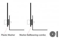
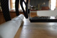
I consider the balance point of this setup to be 3 or 4 centimeters into the camera body. Yes the more I think about it it can also be mechanical or its a combo. The only thing I am wondering about is that tests in my hands producing the nick compensation the gimbal actually moves very smooth. The part that causes friction and worries me is the left washer (see attach foto.) I would love to change it with a special ball bearing, like shown in the drawing but i dont know if they exist or what they are called.
View attachment 545
View attachment 544
The lense weighs 385g plus plastic lense proctection, lets say 10 - 15 g = 400 g
Canon 500 D or Rebel Ti1 480 g without battery, plus bat 50 g = 530 g
I consider the balance point of this setup to be 3 or 4 centimeters into the camera body. Yes the more I think about it it can also be mechanical or its a combo. The only thing I am wondering about is that tests in my hands producing the nick compensation the gimbal actually moves very smooth. The part that causes friction and worries me is the left washer (see attach foto.) I would love to change it with a special ball bearing, like shown in the drawing but i dont know if they exist or what they are called.
View attachment 545
View attachment 544
Attachments
Bartman
Welcome to MultiRotorForums.com!!
guys,
if you can find a regular thrust bearing the hole can be drilled to match the ID of the bearing and just use that size screw through the hole. the bearing will fit snugly through the bearing and each face of the bearing will be in contact with the two sides of the mount.
you can start here for an appropriate bearing.
http://www.bocabearings.com/bearing-types/thrust-bearings
Bartman
Welcome to MultiRotorForums.com!!
this one will slide onto a 4mm screw and takes up 3.5 mm of width with an outside diameter of 8mm
http://www.bocabearings.com/bearing-inventory/thrust-bearings/16425/f48gx-4x8x35
you can always add a washer or two if the thickness isn't exactly right.
http://www.bocabearings.com/bearing-inventory/thrust-bearings/16425/f48gx-4x8x35
you can always add a washer or two if the thickness isn't exactly right.
BorisS
Drone Enthusiast
okay great i got 2 different kinds in different sizes:
http://www.kugellagershopberlin.de/...=71&pname=axialrollenlager-axk0619--6x19x4-mm
and
http://www.bocabearings.com/bearing-inventory/Thrust-Bearings/8014/F614G-6x14x5
lets see which work best.
Thanks ! Boris
http://www.kugellagershopberlin.de/...=71&pname=axialrollenlager-axk0619--6x19x4-mm
and
http://www.bocabearings.com/bearing-inventory/Thrust-Bearings/8014/F614G-6x14x5
lets see which work best.
Thanks ! Boris
I consider the balance point of this setup to be 3 or 4 centimeters into the camera body.
I'm slightly concerned by your use of the word "consider" here
") - do you mean that's a "guess" at where the CG of the camera is?
- do you mean that's a "guess" at where the CG of the camera is? For optimum performance the camera should be pretty close to "perfectly balanced" within the gimbal. It's a one-time, three-step procedure:
1. Remove the gear/belt that's between the pitch servo and the pitch axle so the plate can swing freely. With the camera mounted, adjust it's forward/backward position on the plate until it no long wants to flop forwards or backwards when you let go of it. Temporarily mark the position of the tripod screw on the underside of the plate so you can easily replace the camera in this position.
2. Now adjust the plate up or down (closer to or further from the pivot point) until the plate, with camera attached, behaves more or less "neutral", i.e. it doesn't just "pendulum" down to the bottom or swing upside down. Similar to balancing a prop - it should just stay wherever you put it, without its own weight making it swing one way or the other. You may not be able to get it that exact, but you should be able to feel when its close to that point. Replace the gear/belt on the servo.
3. Remove the gear/belt on the roll axis so it can swing freely. Now shift the camera left/right on the plate (keeping it in the same fore/aft position) until the plate hangs perfect level. Now you can permanently mark the position of the tripod screw on the underside of the plate - in future, when using that camera with that lens, you can immediately place it in the balance position.
If you want to use a different lens sometimes, repeat step 1 with that lens - you'll probably get a slightly different fore/aft position but 2 and 3 shouldn't change.
Doing this will give the servos a] much less work to do to move the camera, but most importantly b] give the servos the same load to move the camera in either direction.
P.S. Please someone correct me if I got any of this wrong
Last edited by a moderator:
BorisS
Drone Enthusiast
japp totally right I was a little sloppy on that and I will do that. I didnt consider a 20 30 40 g. difference to be a big issue since i never balanced the gopro and things worked. But the difference lies in the overall weight of the camera which i didnt consider. The heavier the more important its balanced. The nick balancing should not be a problem I am just worried about the roll axis there are not to many options were i can place the cam in the gimbal due to the fixation holes in the gimbal.
This whole holes in the gimbal to mount the camera due to different models and lenses seems to be a not 100% percent accurate approach to balancing out a cam anyways.
haha but I looking at it now i first have to balance the gimbal itself
Okay no chance with the given holes in the gimbal i will have to add weights to the gimbal to balance it with the cam.
Last edited by a moderator:
Yes - absolutely right - and I'm sorry I forgot to mention it - use weights to fine-tune. Go and ask a car tyre workshop if you can buy a handful of the lead weights they use - they have adhesive backing already on them B) Doesn't have to be super-exact, but the closer the better.
BorisS
Drone Enthusiast
I am going to glue velcro strips on the bottom, front and backside of the gimbal and the negative to some weights, that should make it quickly adjustable for different cam and lenses !
Thanks for the ideas.
perfect: http://shop.rc-hp.de/Much-More-Bleigewichte-4x10g-und-4x5g
Thanks for the ideas.
perfect: http://shop.rc-hp.de/Much-More-Bleigewichte-4x10g-und-4x5g
Last edited by a moderator:
BorisS
Drone Enthusiast
In the best case i need 50 g for balancing out the gimbal (x-axis) with the Canon 500D lens 10-22mm, that doesn't make me happy and cant be it ! Gotta think of a way to position the camera in a more balanced position, although the plate holes and slots don´t allow a better position. Why in the first place construct a gimbal that is not balanced by its own weight and axis and doesn't and probably will never be able, due to stability reason, give the freedom to mount the camera in every possible position. If the only mounting point falls on to the heavier side of the gimbal ones needs even more weights to balance the gimbal, I though this whole game is about reducing weight.
Of coarse is reduces the weight needed if the heavier side over the balance point falls on the lighter side of the gimbal, but i would prefer a balanced gimbal from start. Haven't even looked at the Roll axis yet. I really hope that the camera screw thread is positioned at a balanced spot which again is irrelevant once a heavier lens is mounted, in those cases, like with the Canon 500 D, were the screw thread is not in the middle of the cam.
Of coarse is reduces the weight needed if the heavier side over the balance point falls on the lighter side of the gimbal, but i would prefer a balanced gimbal from start. Haven't even looked at the Roll axis yet. I really hope that the camera screw thread is positioned at a balanced spot which again is irrelevant once a heavier lens is mounted, in those cases, like with the Canon 500 D, were the screw thread is not in the middle of the cam.
BorisS
Drone Enthusiast
Dave i cant tell you yet. The plan is to change all the plastik washer on the AV 200 to thurst bearing. To balance out the gimbal and i am setting up a construction from which i can hang the AD 8 HL and balance it out from head to toe. Once i have all the parts i will report !
Support plate, anti vibration gel certainly improved the performance !
Boris
Support plate, anti vibration gel certainly improved the performance !
Boris
BorisS
Drone Enthusiast
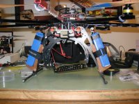
will have to change setup and but PH in the middle and either two lipos on the booms or before and after the ph. Although i prefer on under the booms like in this video: http://vimeo.com/26542588
does anything speak against it ?
View attachment 576
does anything speak against it ?
View attachment 576
Attachments
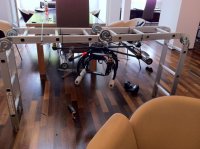
In an ideal setup, the batteries would be mounted to the "stationary" part of the gimbal, or at least somewhere where they are are on the same side of your isolation mounts as the gimbal/camera. The strong contributor to damping/isolation from vibration is to increase the mass of the object you are isolating. Would that be possible here? Not sure of the suspension/isolation arrangement on Droidworx/PH - is it already that way or could you make it that way?
View attachment 577
View attachment 577
Attachments
BorisS
Drone Enthusiast
japp your right i am going to mount the lipos to the landing-gear i think that makes more sense ! Two small carbon plates with velcro straps and that should be it. Additionally i am going to add the vibration gel between the come together of the center plate and the landin-gear, maybe instead or additionally to the rubber pads that are there.
Guys whats a basic cheap setup to cut carbon in a straight line 1 2 3 mm plates. Don't want to get into the whole cnc thing just a simple straight line is what i would need ?
Guys whats a basic cheap setup to cut carbon in a straight line 1 2 3 mm plates. Don't want to get into the whole cnc thing just a simple straight line is what i would need ?
Bartman
Welcome to MultiRotorForums.com!!
FWIW, i modified my MKTR to hold the batteries since it doesn't have mounts for two batteries built into it
maybe the pic will heView attachment 598lp?
maybe the pic will heView attachment 598lp?
Attachments
BorisS,
I would love to see pictures of your battery setup once you are complete. I do not like the idea of droidworx battery holder with the one strap.
Are you going to center mount your camera gimbal or leave it hanging in the front? Might see your skids with it center mounted. However, if you had all weight focused in the middle it could be easier to balance. Just a guess though, and I'm a newb. Curious about your progression because I am currently building a AD8 HLE for photography.
Thanks.