Aeronavics / Droidworx Soldering ESCs to Powerboard - LED and IMU Dbl Tap?

SMP

Member
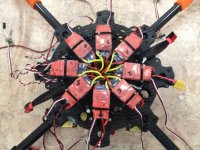
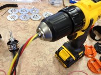
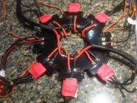
Tore apart the AD6 last night and converting to X8 Coax. This will be my first quasi build (AMP-RTF) so am in uncharted territory. The powerboard is an AD8 board so I have two spare slots for the ESC. Thats good. But the tabs are currently occupied with leads for LEDs on one and the DJI IMU Power on the other. Plan is to lift the LEDs/IMU off the tabs to clear the way for the ESC but then what. I would like to branch the LED/IMU power from the board. So here are my questions. Is it safe to dbl tap (Solder ESC to Tabs and then side solder the taps off the ESC tabs). Are the little holes conductive or just the tabs? Side solder the IMU power from an ESC tap and then run a separate LED batt? Thanks guys, all help very much appreciated!!
View attachment 10909
 

Attachments

  • IMG00817-20130406-1837_1.jpg
    IMG00817-20130406-1837_1.jpg
    148 KB · Views: 282
Last edited by a moderator:

Bluerex

Member
The little holes are plate-through (thru) connections to the other side of the PCB. Just keep the wire close together and make sure the joint is "wet" when soldering - good to go :)

c
 

SMP

Member
Thanks Blue, although now I'm REALLY confused. So on the little holes, can you solder to them by filling up the little hole and then jamming the wire in (or on but with solder making the connection through the hole)???? Or just leave the little holes alone and dbl tap to the ESC/Board tab connection.
 

Bluerex

Member
I would just leave the little holes alone (they are electroplated internally and act as a way of joining the two sides of the PCB together).
Just solder an additional wire beside the ESC wire on the same pad - BUT make sure that the whole joint is "wet" and use a big enough iron to flow the solder across both wires at once.

Unfortunately I never photographed the completed underside of my power board :upset: but you can just see my aux taps for lights, Hitech receiver and the WKM coming out from between the ESC legs. I also soldered my motor wires directly to the plushies.

View attachment 10947
 

Attachments

  • IMG_0952.jpg
    IMG_0952.jpg
    145.7 KB · Views: 191
Last edited by a moderator:

SMP

Member
NOW I'm with you Bluerex!! thanks for the explanations!! Just curious... Is there any particular theories as to what wires you should (and/or shouldnt) twist to reduce noise??
 

Bluerex

Member
To be perfectly honest, I am not sure how effective a practice it is. But I twist everything (the chicken soup principle - it may not do any good, but hey it can't hurt). Logically high current runs would radiate, low current could be susceptible extraneous EMF ... BUT without definite data (and maybe experimenting with ferrite beads etc) I'll keep twisting where I can cause if nothing else it looks neat. I use a battery drill to GENTLY spin the cables together once I have wrapped a bit of tape or heatshrink around the end. Just make sure you hold the wires firmly in your other hand just before they hit the motor to stop them twisting off and escaping :frog:

View attachment 10982View attachment 10983View attachment 10984View attachment 10985
 

Attachments

  • IMG_0938.jpg
    IMG_0938.jpg
    148.9 KB · Views: 280
  • IMG_0935.jpg
    IMG_0935.jpg
    148.3 KB · Views: 327
  • IMG_0937.jpg
    IMG_0937.jpg
    142.2 KB · Views: 295
  • IMG_0936.jpg
    IMG_0936.jpg
    142.1 KB · Views: 320


Top