I know it is very stupid.
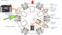
I got one of these.
http://www.electriflite.co.uk/store17/index.php/mount-gps.html
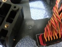
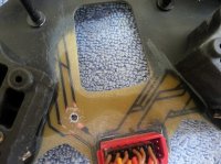
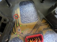
Then I realized that the screw does not fit to any of the wholes of S800 top board. One moment I totally forgot that the top board is somehow a circuit board (distributing power to ESCs). I drilled a little whole on the plate (on the green spot image below).
View attachment 13245
Screwed the thing in place. Powered and boom! A spark went off the GPS mounting place. I realized what mistake I had done. Dismounted the GPS. Powered S800 again and everything is still working. Ran the motor check one by one via wkm software. Motors run. Since the motor check only runs motors in low speed I don’t dare to fly it now. I don’t know if the defect circuit will still handle to feed full power to related ESC while 7kg s800 is off the ground.
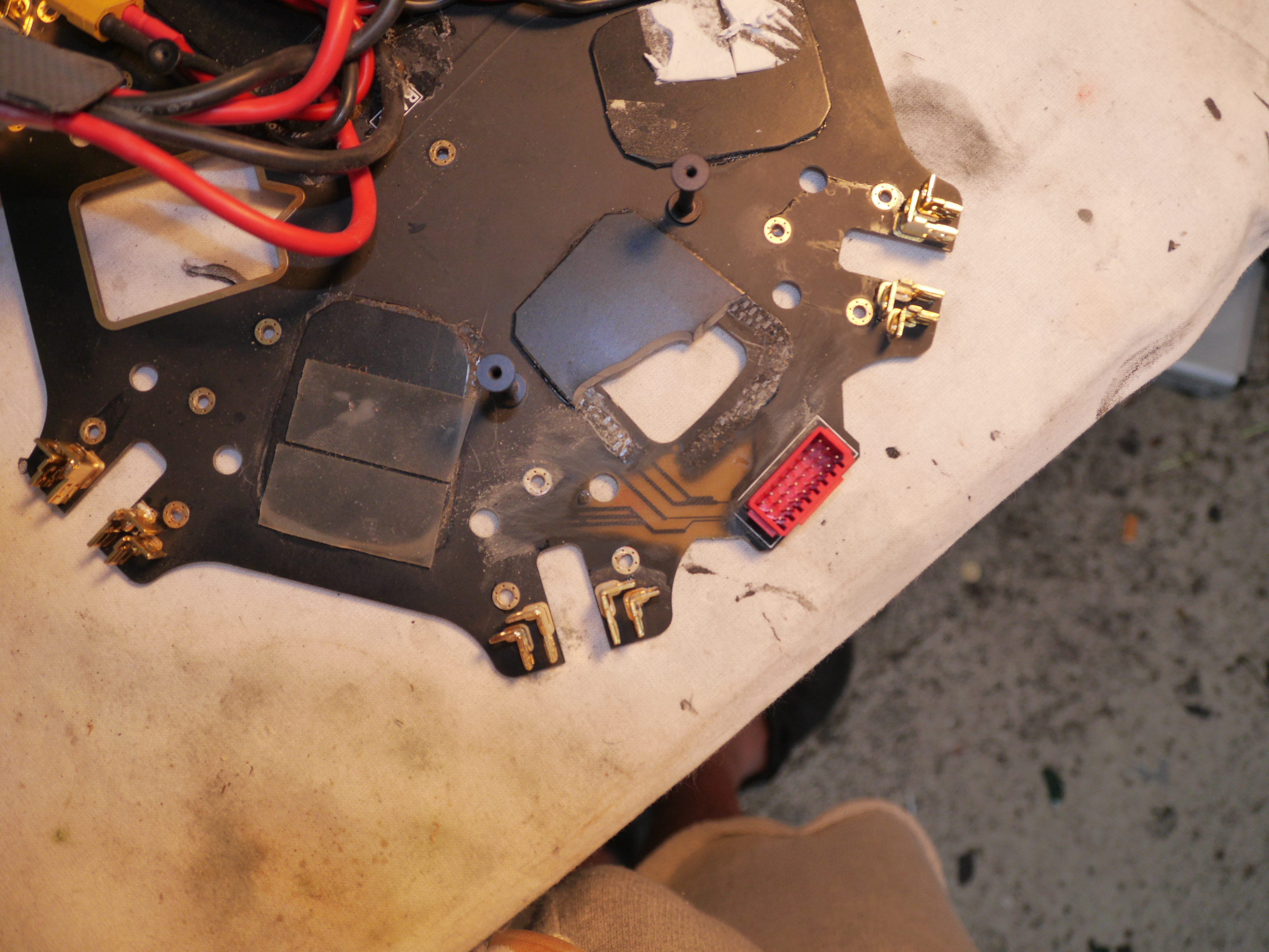
I got one of these.
http://www.electriflite.co.uk/store17/index.php/mount-gps.html
Then I realized that the screw does not fit to any of the wholes of S800 top board. One moment I totally forgot that the top board is somehow a circuit board (distributing power to ESCs). I drilled a little whole on the plate (on the green spot image below).
View attachment 13245
Screwed the thing in place. Powered and boom! A spark went off the GPS mounting place. I realized what mistake I had done. Dismounted the GPS. Powered S800 again and everything is still working. Ran the motor check one by one via wkm software. Motors run. Since the motor check only runs motors in low speed I don’t dare to fly it now. I don’t know if the defect circuit will still handle to feed full power to related ESC while 7kg s800 is off the ground.