For those interested, I wrote up this detailed procedure for replacing the S800 arms, though the same procedure would be used to replace the ESC for an S800 arm. I want to thank Tony (
www.rcrus.com) and Lawrence (
www.aerialtechnologies.com) for their help in learning how to do this and all the tips and guidance they gave.
1) Unscrew the top and bottom plates on the S800 arm.
View attachment 11587
2) Cut the four arm wires and the three motor wires soldered to the ESC. Be sure to snip the wires as close to the solder joints as possible so as to not shorten the wires unnecessarily. (Note, if you are only replacing the ESC, you may have problems by snipping the wires because they may now be too short to resolder to the replacement ESC. You may have to proceed with steps 3 and 4 and clean off the area first, and de-solder the wires to keep their original length.)
(You will notice from some of my pictures that I did not snip the wires very close because my arm was broken and could not be reused.)
This is where the fun begins:
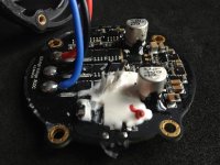
3) Remove the liquid tape that is plastered over the 4 arm wires. In my case, it was white liquid tape, and layered about 2 to 4 millimeters thick. The easiest way I found to do this was to first slice through the rubber with an X-acto knife to make it into smaller cubes. Then with a combination a tiny needle nose pliers and the X-acto knife, I scraped off the white rubber as best I could, especially in the immediate area around the solder joints.
View attachment 11588
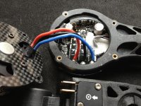
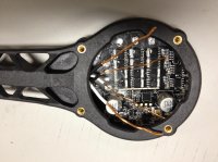
4) Remove the hemiseal layers over all the solder joins and surrounding area. This is a thin transparent film covering the whole board, including the seven solder joints. Obviously, you only want to remove the stuff from the solder joints, but you’ll want to clear a 2 to 3mm area around the joints to ensure you will get clean new solder joints later on. I used a combination of my finger nail, and the X-acto knife.
Between steps 3 and 4 above, I spent about 30- 45 mins per arm to clean off the solder pad area nicely. My first arm was longer than that, but subsequent ones took less. The required time was also directly related to how think the liquid tape was layered. One of mine was about 5mm thick, and took me a lot longer. You will want to ensure the area is cleaned off nicely because any remaining liquid tape or hemiseal makes the de-soldering process that much more difficult since these also prevent the soldering iron’s heat to reach the solder, and/or burns giving off bad smoke/smell.
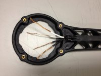
5) To ensure further insulation between the wires, I added about 1/2" of heat shrink and pushed it right up to where the wires come out of the arm. The reason I do this is to just further insulate and separate the wires as they cross each other to keep the vibration from rubbing off the little insulation that is on the wires. Note that, depending on when you bought your arms, the wires through the arms may have a thin transparent insulation, or they may have colored insulation. My replacement arms had the thin transparent insulation, and the heat shrink I used was white and black (to differentiate the side of the arm the wires came out of).
View attachment 11589
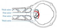
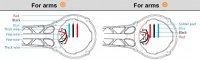
6) Layout the wires from the new arms. You will notice that a thick and thin wires comes out of each side of the arm. Throughout this process, it is important that these wires be soldered to their original points on the ESC board. Regardless if the arm is an ‘X’ or an ‘O’ arm, the soldering from the arm to the ESC is the same. You will notice from the diagram (from DJI) and photos below that the wires actually will cross each other. (In my opinion, this is a design flaw in the arm because now the wires will be rubbing against each other with the vibration, and could be problematic.)
View attachment 11590View attachment 11591
6) Once you’ve laid out the arm wires, you can trim them to length and prepare them for soldering. Be careful not to trim them too short because there is no regrowing of these wires once you trim them.
7) Once trimmed, you need to prepare the arm wires for soldering. If you have wires with normal insulation, this is a simple stripping process. However, if you have the transparent coated motor wires (like I did above), you will need to remove the coating in some other fashion. I’ve heard of people using a tiny drimmel tool, I’ve heard of sand paper, but what I ended up using was my trusty ol’ X-acto knife again. This is not as easy as it sounds because you need to ensure you scrap off this coat all around the wire. Any area of the wire that has not been scraped off will prevent the soldering from adhering.
Steps 8 and 9 below can be done in either order. For me, I found doing 8 then 9 a little bit easier.
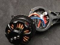
8) Solder the motor wires to the ESC board. Remember, you must run the wires through the arm before soldering! Strip off the last 3-4mm of the end of the wires, and tin them with your soldering gun. Then proceed to solder the three motor wires to the ESC soldering pads per the diagram (from DJI) below. As you will notice from the original way the wires were soldered, the wired should point towards the middle of the ESC board so that they do not interfere with the S800 arms once you screw it to the arm.
View attachment 11592
It is also important to note that how you wire the motor to the ESC is the only difference in the ‘X’ versus ‘O’ arms. Even though the arms have a plate screwed on it indicate ‘X’ versus ‘O’, there is no difference in the arm itself. You can unscrew this plate and apply to another arm if you so choose. Just ensure the soldering of the motor to the ESC matches the plate on the arm.
9) Solder the arm wires to the ESC board. For this, I found it easiest to screw the ESC board into the arm so that the board and arm are not moving around during the soldering process, especially since soldering these four wires is going to be in a very confined area.
10) Coat the solder joints with liquid tape. You can buy liquid tape from Home Depot, and Amazon. You may get some funny faces at Home Depot when you ask, but you’ll find it in the electrical area.
View attachment 11593
11) Obviously, screw top and bottom plate tightly to the S800 arm.