Power distribution boards, ratings question

Bartman

Welcome to MultiRotorForums.com!!
Surfing around the internet I'm looking at the different power distribution boards that are out there.

Photoship One makes one
http://photoshipone.com/shop/index.php?main_page=product_info&cPath=40&products_id=250

MultiWiiCopter makes one as well
http://www.multiwiicopter.com/products/voltair-esc-wiring-board

The one from PhotoshipOne is rated for 60 amps with one battery and 80 amps with two. So, if I understand this correctly, that's 10 amps max per set of motor connections if you're using two batteries? That doesn't seem like a lot considering the popular Tiger motors are rated to a max of 25 amps at 14.8 volts.

The MultiWii board is only rated to 60 amps (no mention of number of batteries is made).


It seems that the max amp rating is determined by what the battery contacts can handle. If the battery contacts are of the same design as the motor pads (like with the MultiWii board), then wouldn't using two pads per battery connection effectively double the rating? If I brought the negative from a battery into the board using two contacts and same for the positive, times two for two batteries, I'd have four sets of contacts supplying power to the board with each contact rated for 60 amps.

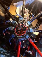
I have a simple wire harness already built but I'm trying to incorporate a power board just for ease of assembly.

Thanks,
Bart


DucktileMedia

Drone Enthusiast
One thing I dont like about almost all the power boards I see is that the positive and negatives are way too close to each other. I am gonna stick with using 2 plain steel washers. They are very easy to solder to and are not going to have any issues with power.
 

Lanzar

Member
Maybe it would be easier just to solger everithing on one side together with lost of solgering material and for shure u will get a board with more than 200 amps. Just add a lot :)


jes1111

Active Member
That won't work, Bart. The current flowing through the board will still be the same. All these PDBs rely on "sailing close to the edge", i.e. technically they can't handle the current but can "get away with it" because the peaks exist for only short periods and there's (hopefully) time for it to cool down before the next peak. Personally I would equate that to "Russian Roulette". The "gotcha" is that resistance rises with temperature, so there will be a point at which the temperature is already high enough that the next peak raises the temperature exponentially - effectively a "run-away reaction" - and the outcome is that stuff starts to melt.

PCBs with sufficiently heavy copper to handle these sorts of currents are hard to source, particularly as plain "prototype board". I'm making my own by bonding 0.5mm copper sheet to 1.6mm FR4 (for reasons other than "convenience").
 

Bartman

Welcome to MultiRotorForums.com!!
thanks for the replies everyone. if someone has an idea they'd like to try I've been working with a waterjet shop and could have copper sheet cut. I'd need an autocad drawing to get it moving,.

back to the wiring harness, not that there's anything wrong with that. :)


What build are you using this in Bart? Motors, hex or octo?, cell count? I'm in the same boat wondering what to use.

Tristan
 

Bartman

Welcome to MultiRotorForums.com!!
What build are you using this in Bart? Motors, hex or octo?, cell count? I'm in the same boat wondering what to use.

Tristan

The build is an XY8 coaxial quad using the Hoverfly Pro flight control system. I had one flying (It threw a prop and motor bell then came down hard enough to break an arm) but I used my Mikrokopter frame and adapted it. This new one is with the Hoverfly specific frame plates which have provisions for mounting a power board in the center under the FC board. Motors are Tiger 2814's. The power board should make it all go together very neatly and make it easy to pull motors or ESC's when necessary. I've got it built using the PhotoShipOne board but I don't think it will be robust enough for the workload so I'll have to pull it apart and wire it with a harness for now. I've ordered two of the MultiWii boards and I think they can be modified to handle my application's power needs.

Bart
 

xtrmtrk

Member
thanks for the replies everyone. if someone has an idea they'd like to try I've been working with a waterjet shop and could have copper sheet cut. I'd need an autocad drawing to get it moving,.

back to the wiring harness, not that there's anything wrong with that. :)

Wow, that's super nice of you to offer that. I may contact you with some drawings. I wonder if I can I convert Illustrator to AutoCad?

Does anyone know of a good way to bond copper to G10?
 

Bartman

Welcome to MultiRotorForums.com!!
Wow, that's super nice of you to offer that. I may contact you with some drawings. I wonder if I can I convert Illustrator to AutoCad?

Does anyone know of a good way to bond copper to G10?

i believe you can export an illustrator file to .dxf format and then import it into Autocad.

I was thinking of cutting the copper with tabs that could be bent 180 degrees back onto a board of some sort. it's a challenging design as you could just solder everything before assembling the board but then how would you remove wires to do repairs without melting everything together? the underlying material would have to be very temperature resistant.

bart
 

jes1111

Active Member
Regular PCBs have the copper bonded to the FR4 with epoxy. In reality, it is designed to soften/melt whilst being soldered and re-harden once the heat source is removed. This is why you'll sometimes displace very small pads when trying to solder to a PCB. Choose a low viscosity epoxy (of average/normal heat resistance) and apply as much pressure as possible (evenly) when bonding - for example, using G-clamps and two sheets of 19mm MDF to squeeze the sandwich while it is curing. A minimum of 24 hours later, you can pretty much treat it like any other PCB: drill it, mill it, solder it, etc. - although I think you'd have to work hard to etch it! Good soldering technique - applying the minimum amount of heat for the minimum amount of time will help, of course.
 

CineRebel

Member
This is how I did it for my skyjib 8 ... I dont like using connectors and boards... just a AWG10 wire is the safest way! View attachment 4549

You can easily connect 2 lipos at each end of the cable and you have minimum soldering!
 

Attachments

  • photo.jpg
    photo.jpg
    147.7 KB · Views: 382


Top