Photronix
Pilot
This is re-posted from RCgroups. I wanted to share it with you guys as well.
I've watched the debate over the "speed" and performance of ESCs here for a while. I also see a great deal of effort being spent re-flashing ESCs to improve factory firmware capabilities. The general consensus has been that how fast the propeller can react to a flight controllers commands is directly related to the performance of a multi-rotor. This is true somewhat, but the blame for poor performance has been placed on the ESC mostly. This is incorrect simply because the ESC, Motor, Propeller combination sub-system that actuates the system needs to be considered as a whole. I do not believe the ESC is the bottleneck but rather the drive sub-system.
So about a year ago I set out to measure the Transfer Function of the ESC, Motor, Propeller subsystem since as a flight controller designer this is what is important to me. In engineering, Transfer Function is one of the most common figures-of-merit which is used to compare and measure a systems performance.
What is Transfer Function? Simple.. it is a measurement of a systems response to a known input. I've seen tests where the motor is hit with a step change in throttle. This is a great measurement. Transfer Function is then the derivative of the time measurement which is then Fourier Transformed to yield the Transfer Function (actually this is the magnitude of the previous). The easiest and best way to measure Transfer Function is to drive a system with a sinusoidal input and measure the time varying sinusoidal output. The modulation depth is then measured using the amplitude of the output waveform.
So my test stand optically measures the RPM (as my output value) of a common RC brushless motor (BL-2217/9) 16 times per revolution. I used a APC 10x3.8 propeller. A microprocessor drives several different ESC models with a sinusoidal signal at 200Hz. This may be confusing...the signal is the throttle input to the ESC which varies in time sinusoidally. I chose to use an average throttle value at 50% (hover in most multi-rotors) and vary the throttle 25% above and below this point. Using a larger or smaller value doesn't actually change the result much.
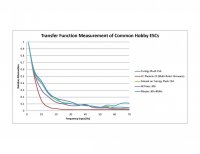
The resulting Transfer Function is a curve showing Relative Attenuation vs. Input sinusoidal frequency. To compare performance of the ESCs you can pick a frequency, say 30Hz and observe the attenuation seen for each ESC. A lower value means that the sub-system was unable to output a sine wave as large in amplitude as another ESC with a higher value.
The results are attached. Let me point out a few things.
1. Turnigy had the best overall response with an almost identical curve for the re-flashed Simonk Turnigy. Does this mean the re-flash is a waste of time? You decide...I am just presenting the data.
2. The Castle Creations Multi-Rotor firmware is cutting off at too low a frequency. They are working on this now and I fully expect them to be able to match the Turnigy curve. I'll post new results when I get them.
3. The Maytec 400Hz performs as well as the Turnigy but I wouldn't use it. At around 65Hz it begins to exhibit aliasing. This is when higher input frequencies are folded around a sampling frequency and result in a lower frequency being output. At 65Hz you will see about 20Hz oscillation which is BAD for a multirotor.
4. Smaller Props and faster motors will provide better performance. However, it will simply raise up the curves maybe 5%. Their relative shapes will remain the same.
5. The older Castle Creations firmware (data not shown) exhibits extreme aliasing after 50Hz. This is why the older firmware did not work on multi-rotors. The flight controllers where sending out commands with changes above 50Hz which resulted in very low frequency changes in RPM. Not what your basic flight controller expects and as a result FAIL.
6. Faster I2C communication is not needed based on this test because the actually ability to alter a motor/propellers speed is around 30Hz.
7. If your contention is that your multi-rotor performs better with one ESC over another it may be the flight controller or another part of the system.
8. RCTimer is the lowest performer assuming CC updates their firmware.
View attachment 3442
I've watched the debate over the "speed" and performance of ESCs here for a while. I also see a great deal of effort being spent re-flashing ESCs to improve factory firmware capabilities. The general consensus has been that how fast the propeller can react to a flight controllers commands is directly related to the performance of a multi-rotor. This is true somewhat, but the blame for poor performance has been placed on the ESC mostly. This is incorrect simply because the ESC, Motor, Propeller combination sub-system that actuates the system needs to be considered as a whole. I do not believe the ESC is the bottleneck but rather the drive sub-system.
So about a year ago I set out to measure the Transfer Function of the ESC, Motor, Propeller subsystem since as a flight controller designer this is what is important to me. In engineering, Transfer Function is one of the most common figures-of-merit which is used to compare and measure a systems performance.
What is Transfer Function? Simple.. it is a measurement of a systems response to a known input. I've seen tests where the motor is hit with a step change in throttle. This is a great measurement. Transfer Function is then the derivative of the time measurement which is then Fourier Transformed to yield the Transfer Function (actually this is the magnitude of the previous). The easiest and best way to measure Transfer Function is to drive a system with a sinusoidal input and measure the time varying sinusoidal output. The modulation depth is then measured using the amplitude of the output waveform.
So my test stand optically measures the RPM (as my output value) of a common RC brushless motor (BL-2217/9) 16 times per revolution. I used a APC 10x3.8 propeller. A microprocessor drives several different ESC models with a sinusoidal signal at 200Hz. This may be confusing...the signal is the throttle input to the ESC which varies in time sinusoidally. I chose to use an average throttle value at 50% (hover in most multi-rotors) and vary the throttle 25% above and below this point. Using a larger or smaller value doesn't actually change the result much.
The resulting Transfer Function is a curve showing Relative Attenuation vs. Input sinusoidal frequency. To compare performance of the ESCs you can pick a frequency, say 30Hz and observe the attenuation seen for each ESC. A lower value means that the sub-system was unable to output a sine wave as large in amplitude as another ESC with a higher value.
The results are attached. Let me point out a few things.
1. Turnigy had the best overall response with an almost identical curve for the re-flashed Simonk Turnigy. Does this mean the re-flash is a waste of time? You decide...I am just presenting the data.
2. The Castle Creations Multi-Rotor firmware is cutting off at too low a frequency. They are working on this now and I fully expect them to be able to match the Turnigy curve. I'll post new results when I get them.
3. The Maytec 400Hz performs as well as the Turnigy but I wouldn't use it. At around 65Hz it begins to exhibit aliasing. This is when higher input frequencies are folded around a sampling frequency and result in a lower frequency being output. At 65Hz you will see about 20Hz oscillation which is BAD for a multirotor.
4. Smaller Props and faster motors will provide better performance. However, it will simply raise up the curves maybe 5%. Their relative shapes will remain the same.
5. The older Castle Creations firmware (data not shown) exhibits extreme aliasing after 50Hz. This is why the older firmware did not work on multi-rotors. The flight controllers where sending out commands with changes above 50Hz which resulted in very low frequency changes in RPM. Not what your basic flight controller expects and as a result FAIL.
6. Faster I2C communication is not needed based on this test because the actually ability to alter a motor/propellers speed is around 30Hz.
7. If your contention is that your multi-rotor performs better with one ESC over another it may be the flight controller or another part of the system.
8. RCTimer is the lowest performer assuming CC updates their firmware.
View attachment 3442
")