Bartman
Welcome to MultiRotorForums.com!!
Hi gang,
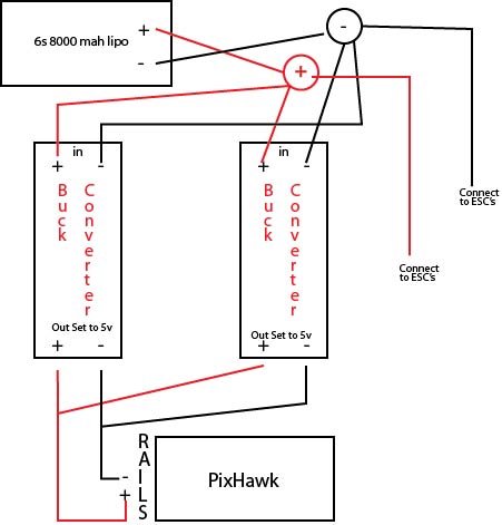
We were talking about supplying power to a 3DR Pixhawk unit and a traditional method is to use power from the flight batteries reduced to 5V via a regulator (aka BEC).
I'd be happy to do that but the common buck converter isn't exactly an example of aerospace manufacturing sophistication. They are surprisingly reliable considering they only cost a buck and are sold by the dozen on ebay but, IMHO, to be a top-shelf power option for a heavier heli's control system, there should be redundancy designed into the system.
3DR recognizes people will want to do this and user @jfro posted a link where someone diagrammed a simple dual-regulator arrangement
http://drones.webstanz.be/blog/pixhawk-flight-controller-power-recommandations
So the basic premise is to use two buck converters in parallel with diodes to keep one's output from affecting the other's but can we do better by maybe conditioning/smoothing the output with capacitors and using LED's to indicate the BEC's are working (since a failure of one wouldn't keep the flight controller from operating normally but would eliminate the safety net of having two in parallel)??
Anyone want to chime in on sizing and positioning capacitors or LED's in circuit?
Bart
We were talking about supplying power to a 3DR Pixhawk unit and a traditional method is to use power from the flight batteries reduced to 5V via a regulator (aka BEC).
I'd be happy to do that but the common buck converter isn't exactly an example of aerospace manufacturing sophistication. They are surprisingly reliable considering they only cost a buck and are sold by the dozen on ebay but, IMHO, to be a top-shelf power option for a heavier heli's control system, there should be redundancy designed into the system.
3DR recognizes people will want to do this and user @jfro posted a link where someone diagrammed a simple dual-regulator arrangement
http://drones.webstanz.be/blog/pixhawk-flight-controller-power-recommandations
Advanced configuration
: triple redundant power sources (power module as primary , plus two backup BECs – instead of one- to power Pixhawk’s servo rail):
A simple Tie bus circuit can be used to make the secondary power source redundant ! (therefore the power module can fail, a secondary BEC can fail while the third BEC will take over). In this scheme, a simple MBR1545CT integrated circuit is used. This circuit takes two BEC on its inputs and outputs only of of the two BEC according to the highest voltage (i.e. if BEC1 outputs 5.25V and BEC2 outputs 5.45V, MBR1545CT will pass BEC2 and blocks BEC1).
Here a tie bus circuit wiring diagram and example realisation with the MBR1545CT integrated circuit and a 6 pin JST connector:

So the basic premise is to use two buck converters in parallel with diodes to keep one's output from affecting the other's but can we do better by maybe conditioning/smoothing the output with capacitors and using LED's to indicate the BEC's are working (since a failure of one wouldn't keep the flight controller from operating normally but would eliminate the safety net of having two in parallel)??
Anyone want to chime in on sizing and positioning capacitors or LED's in circuit?
Bart
")