Deans are killing my fingers!!!

Bartman

Welcome to MultiRotorForums.com!!
..........I wouldn't recommend using it unless you are a ninja with the soldering iron :)

Jes, you have to admit, you have a tendency to overstate things a bit, no? :)

i'm using the Radio Shack solder #64-009, it's 60/40 rosin core, .032" diameter. I assume it contains lead because it doesn't say lead-free as some of the others do.

With soldering, as the joint and solder reaches full heat you'll see the rosin/flux boil out which is fine. If you're going to go back and do any work to the joint you'll have to reintroduce rosin/flux either from another source such as a separate tin, a flux marker, or by adding a bit more solder. Without rosin/flux, the solder gets clumpy and will stick to the soldering iron.

There's a fine line in any of this between too much heat and too little heat. Often, it is knowing where to put the heat that makes the difference as in my little video above.

Bart
 

Lifter

Member
The TP batteries don't seem to live up to the high price. Nano-techs deliver great power deep into the discharge cycle, they're cheap, relatively light........i don't understand the bashing of cheap batteries when they actually work really well.

I meant cheap compared to the TP's.

Have had this single battery draining problem since new and it came with the 4500 Nano Tecs, thought it was initially the Nanos being faulty so tried the Hk blues then the TP's - didnt make any difference.

Still does it but not every time but I cant trust it not to, hence the search for for the Power pole and to test them to see if the problem still arises without the Deans connected.
Cheers
Alan


jes1111

Active Member
According to this: http://rcfoamfighters.com/blog/?p=84 the max amps that can be drawn from my lipo 5400mah 35c lipo is 189. That means even the EC5 (120 amps) connectors are not as suitable as a I thought or does it not matter so much?

I have not come accross any connectors that are above 120amps. Anyone know of any?

189A may well be the maximum capability of your battery pack, but the actual current drawn will depend on your rig. Hopefully it will be less than 189A, otherwise you'll have problems with the battery! :)

The amperage "rating" of a connector (as well as the wire) assumes a certain temperature rise. Current flowing through a resistance will always produce heat. In the technical world, "current rating" will also specify the temperature rise (e.g. 80A , 30ºC rise above ambient). The RC world rarely specifies the temperature rise, so the "rating" is often meaningless.

Essentially, the objective with a connector is to provide roughly the same resistance to the flow of current as the wires either side of that connection. Therefore it is equally important to know the wire gauge(s). There would be little point in using a connector with a higher "rating" than the wires, but it's definitely asking for trouble to use a connector with a lower rating than the wires. So, first off, you should be considering the total amperage capability of your wiring, not just the connectors.

Consulting the widely-available wire capacity charts tends to lead to confusion. Particularly for household wiring (which is what most charts are showing) it's assumed the wire is enclosed (in a conduit, for example) and therefore has very little heat dissipation capability. Furthermore, the "rating" is likely to be for a very low temperature rise (makes sense - you don't want the wires buried in the walls of your house getting hot, right?). So, for RC applications, none of those available charts really apply. We (usually) have the wires in open air, often with airflow over them, so they can dissipate heat much more readily. We use silicone-sleeved wire because it can withstand around 200ºC before melting. So temperature rise of, say, 60ºC over ambient would be acceptable (though not desirable). Of course, you have to choose and build your wiring system to cope with the maximum current that will flow through it. But when flying around normally - hovering and a bit of maneuvering for AP, for example - the actual current flowing will be substantially less, so we shouldn't be experiencing significant heat rises in the wires or connectors. They can be "warm" after a flight, but if they are "hot" then you probably have something wrong.

If your battery comes with 10AWG wire then you need a connector that has at least the same capacity. You also need to make sure that your wires are also 10AWG from there through to the point where the current is split to go to each ESC (which could be a power distribution board or a soldered spider). If you build a parallel-pack Y-piece then the "tail" (which now has to carry the total current coming from both batteries) should be at least one AWG size bigger - e.g. 8AWG. In reality I wouldn't recommend that approach, though. It would be much better to run two, separate 10AWG wires all the way to the "split off" point.

So, really, it comes down to the question: what connector can handle the same current as a 10WG wire? My (unscientific) answer is: EC5, 4-5mm (or bigger) bullets (depending on design/quality), PowerPole 45A (or bigger), maybe XT60, maybe Traxxas, maybe a few other proprietary designs. Of these, the only one that has both Primary and Secondary Locking (see my recent post) is the PowerPoles. On that basis alone I choose PowerPoles, but there are other advantages too: crimping is actually a more reliable method than soldering (particularly if your soldering skills are below ninja-level) - it's the prefered method in many aerospace and military applications; they are modular, allowing many stacking and keying options as well as colour coding. They can be surface or panel mounted. There are PCB-mount contacts available, rubber cover caps and so on - you are buying into a whole connector "system".

Back on the subject of ratings - the PowerPole 45 is "rated" at only 45A - does that mean it's not as good as, say, an XT60 with a 60A "rating"? Absolutely not! The "45" actually references the maximum wire gauge that the crimp contact can accept - which happens to be... 10AWG :) (because in a normal scenario that's the maximum continuous current you'd pass through a 10AWG wire). The 30A and 15A versions are the same plastic housing and the contacts are the same at the business end, the only difference being the crimp receptacle part, which is smaller on the 30A and 15A versions to accept correspondingly smaller wires.

Oh - and they're around the same price (or cheaper) than the "specially designed for RC" connectors. Not that price should matter for such an important component ;)

Note: successful use of PowerPoles absolutely 100% requires that you buy the correct crimping tool - about $40.
 

jes1111

Active Member
Jes, you have to admit, you have a tendency to overstate things a bit, no? :)

i'm using the Radio Shack solder #64-009, it's 60/40 rosin core, .032" diameter. I assume it contains lead because it doesn't say lead-free as some of the others do.

With soldering, as the joint and solder reaches full heat you'll see the rosin/flux boil out which is fine. If you're going to go back and do any work to the joint you'll have to reintroduce rosin/flux either from another source such as a separate tin, a flux marker, or by adding a bit more solder. Without rosin/flux, the solder gets clumpy and will stick to the soldering iron.

There's a fine line in any of this between too much heat and too little heat. Often, it is knowing where to put the heat that makes the difference as in my little video above.

Bart
60/40 is a 60% lead and 40% tin mixture - no silver. Solders that include any percentage of silver (there are many variations) require higher heat and tend to adhere less readily that their lead/tin counterparts. Definitely needs more skill (and better equipment) to solder correctly with it, plus you get into issues of flux compatibility, etc. - best avoided IMO ;)

I'd accept the "overstating" label if I didn't back it up with extensive reasoning - and certainly nobody can accuse me of being "brief" ;) I've been spouting on a bit recently because two of my "favourite" subjects have come up - motor bearings and connectors. Anecdotal evidence from around the web, combined with engineering experience and common sense, indicates that these two between them are amongst the most common reasons for falling out of the sky (discounting pilot error). The bearings are the only "moving part" in an MR (in the full mechanical sense of metal-to-metal contact) but you can also count the connectors as a "moving part" in that way - their metal-to-metal contact is vital to the reliability of the craft.
 

Malcr001

Member
189A may well be the maximum capability of your battery pack, but the actual current drawn will depend on your rig. Hopefully it will be less than 189A, otherwise you'll have problems with the battery! :)

The amperage "rating" of a connector (as well as the wire) assumes a certain temperature rise. Current flowing through a resistance will always produce heat. In the technical world, "current rating" will also specify the temperature rise (e.g. 80A , 30ºC rise above ambient). The RC world rarely specifies the temperature rise, so the "rating" is often meaningless.

Essentially, the objective with a connector is to provide roughly the same resistance to the flow of current as the wires either side of that connection. Therefore it is equally important to know the wire gauge(s). There would be little point in using a connector with a higher "rating" than the wires, but it's definitely asking for trouble to use a connector with a lower rating than the wires. So, first off, you should be considering the total amperage capability of your wiring, not just the connectors.

Consulting the widely-available wire capacity charts tends to lead to confusion. Particularly for household wiring (which is what most charts are showing) it's assumed the wire is enclosed (in a conduit, for example) and therefore has very little heat dissipation capability. Furthermore, the "rating" is likely to be for a very low temperature rise (makes sense - you don't want the wires buried in the walls of your house getting hot, right?). So, for RC applications, none of those available charts really apply. We (usually) have the wires in open air, often with airflow over them, so they can dissipate heat much more readily. We use silicone-sleeved wire because it can withstand around 200ºC before melting. So temperature rise of, say, 60ºC over ambient would be acceptable (though not desirable). Of course, you have to choose and build your wiring system to cope with the maximum current that will flow through it. But when flying around normally - hovering and a bit of maneuvering for AP, for example - the actual current flowing will be substantially less, so we shouldn't be experiencing significant heat rises in the wires or connectors. They can be "warm" after a flight, but if they are "hot" then you probably have something wrong.

If your battery comes with 10AWG wire then you need a connector that has at least the same capacity. You also need to make sure that your wires are also 10AWG from there through to the point where the current is split to go to each ESC (which could be a power distribution board or a soldered spider). If you build a parallel-pack Y-piece then the "tail" (which now has to carry the total current coming from both batteries) should be at least one AWG size bigger - e.g. 8AWG. In reality I wouldn't recommend that approach, though. It would be much better to run two, separate 10AWG wires all the way to the "split off" point.

So, really, it comes down to the question: what connector can handle the same current as a 10WG wire? My (unscientific) answer is: EC5, 4-5mm (or bigger) bullets (depending on design/quality), PowerPole 45A (or bigger), maybe XT60, maybe Traxxas, maybe a few other proprietary designs. Of these, the only one that has both Primary and Secondary Locking (see my recent post) is the PowerPoles. On that basis alone I choose PowerPoles, but there are other advantages too: crimping is actually a more reliable method than soldering (particularly if your soldering skills are below ninja-level) - it's the prefered method in many aerospace and military applications; they are modular, allowing many stacking and keying options as well as colour coding. They can be surface or panel mounted. There are PCB-mount contacts available, rubber cover caps and so on - you are buying into a whole connector "system".

Back on the subject of ratings - the PowerPole 45 is "rated" at only 45A - does that mean it's not as good as, say, an XT60 with a 60A "rating"? Absolutely not! The "45" actually references the maximum wire gauge that the crimp contact can accept - which happens to be... 10AWG :) (because in a normal scenario that's the maximum continuous current you'd pass through a 10AWG wire). The 30A and 15A versions are the same plastic housing and the contacts are the same at the business end, the only difference being the crimp receptacle part, which is smaller on the 30A and 15A versions to accept correspondingly smaller wires.

Oh - and they're around the same price (or cheaper) than the "specially designed for RC" connectors. Not that price should matter for such an important component ;)

Note: successful use of PowerPoles absolutely 100% requires that you buy the correct crimping tool - about $40.


Thanks for the input jes1111. As I have already bought EC5 connectors I will just stick with these as they seem to be an acceptable choice. I was just worried that I should had been choosing a connector with a higher amp rating. As the lipo uses 10 AWG wire it made sense to me that I should be using 10 AWG wire accross all the wiring that connects to my power distribution board so I also bought 10 awg yesterday. This will be another job for me. It's amazing, I get a constant stream of tasks I need to do with this quad.
 

Bartman

Welcome to MultiRotorForums.com!!
60/40 is a 60% lead and 40% tin mixture - no silver. Solders that include any percentage of silver (there are many variations) require higher heat and tend to adhere less readily that their lead/tin counterparts. Definitely needs more skill (and better equipment) to solder correctly with it, plus you get into issues of flux compatibility, etc. - best avoided IMO ;)

I'd accept the "overstating" label if I didn't back it up with extensive reasoning - and certainly nobody can accuse me of being "brief" ;) I've been spouting on a bit recently because two of my "favourite" subjects have come up - motor bearings and connectors. Anecdotal evidence from around the web, combined with engineering experience and common sense, indicates that these two between them are amongst the most common reasons for falling out of the sky (discounting pilot error). The bearings are the only "moving part" in an MR (in the full mechanical sense of metal-to-metal contact) but you can also count the connectors as a "moving part" in that way - their metal-to-metal contact is vital to the reliability of the craft.

for what it's worth, how many Deans connectors have been used successfully over the years......millions? they may be designed for RC but what's the point? they work, they're light, and they aren't difficult to solder once you get the right tools and supplies. I've got XT60 connectors in a few places and they're every bit as hard to pull apart as the Deans and will deform just as easily (maybe even more easily) if not soldered correctly. at some point it's beneficial to know when to say enough's enough. double locking, crimping, triple the weight.....i don't care what the justification is, Deans work well and are perfectly suitable for probably all the sport multi's out there and a lot of the pro rigs.

yes, there are other connectors out there but to say Deans are insufficient in some way is just a bit over the top in my book unless we're talking capacity limits which is fine. RC in general suffers from the mentality that more is always better, especially if the price is triple. guys that want to put 6.0 v into their 4.8 v ignition systems, or carbon fiber props where wood is actually better, or 2.4 ghz at a field that never had issues with 72mhz.....it's all kind of silly to me actually.
 

Malcr001

Member
for what it's worth, how many Deans connectors have been used successfully over the years......millions? they may be designed for RC but what's the point? they work, they're light, and they aren't difficult to solder once you get the right tools and supplies. I've got XT60 connectors in a few places and they're every bit as hard to pull apart as the Deans and will deform just as easily (maybe even more easily) if not soldered correctly. at some point it's beneficial to know when to say enough's enough. double locking, crimping, triple the weight.....i don't care what the justification is, Deans work well and are perfectly suitable for probably all the sport multi's out there and a lot of the pro rigs.

yes, there are other connectors out there but to say Deans are insufficient in some way is just a bit over the top in my book unless we're talking capacity limits which is fine. RC in general suffers from the mentality that more is always better, especially if the price is triple. guys that want to put 6.0 v into their 4.8 v ignition systems, or carbon fiber props where wood is actually better, or 2.4 ghz at a field that never had issues with 72mhz.....it's all kind of silly to me actually.

I dont know about you but when I had deans connectors I also used to have trouble actually connecting them. For example as I go to connect them the gold contacts would make contact end-to-end but it requires some accuracy to actually slip both the contacts in the slots of the female deans connector. This meant that I would go try and connect the plug and the contacts touch end-to-end creating a little spark but when I try to move the contacts into the slot I would fail and have to try again lol. Maybe this was just me but I always found that I had to attempt this at least 3 times. I dont have fat fingers either. Xt60's are easier to connect because the female plugs hole acts as a guide helping to connect the plugs first try as you have to the fit the plug in the hole before it makes contact. It may sound silly but I have found this to be true.
 

jes1111

Active Member
Thanks jess1111,

Here is some info and more Pics -

re Q1: It is just "Liquid electrical tape" the shrink wrap wasnt quite in position.

re Q2: Havent noticed any hot wires anywhere, that includes the Deans connectors.

re Q3: "You are using a Y-piece parallel adapter, feeding into a single cable" - Yes correct,
"Where does that cable go to" - only guessing here as it vanishes into the guts of it, would assume it runs to a PDB also its a 12awg wire and its all Mk equipped.

re Q4: The 2 branches of the Y lead are probably 14awg (definitely not 12awg) no markings on the wire and yes 10awg feeding them with 12awg going into the PDB (?) and 10awg leads on the batteries.

In the first Pic you can see the main feed + red wire under the ribbon. That is not the original Y lead, I have swapped / replaced it several times - same prob.

Thanks

Okay - definitely you need to replace basically everything between the batteries and the ESCs :)

I'm not familiar with MK - can someone verify what the ESC/PDB setup is there? It looks like the ESCs are mounted on a PDB but where does the power feed in and is it to a single point or multiple points?

For fairly obvious reasons, I'd avoid using 8AWG wire - but that is what you should be using to join two 10AWG feeds together - I hope you "get" that from my other recent posts ;) The easier and better alternative is to run two discrete, separate 10AWG feeds, one from each battery, all the way to the point of distribution/division (which depends on the answer to my PDB question above).

So you need some 10AWG wire in red and black, some red and black heat-shrink of appropriate size, a good wire-stripper and a PowerPole crimp tool. Plus the PowerPoles. Where are you going to get your supply from? Anderson's own crimp tool is hideously expensive. Powerwerx and MountainRadio sell a reasonably-priced OEM version which does the job just as well. I've seen them on EPray too - can't speak for how well they might work. I buy my connectors from Mouser - cheaper but a bit more fiddly to work out the right part numbers. I have the MountainRadio crimper. Since you need the crimp tool you might as well buy the connectors themselves from the same source. If you can find the whole shebang in Oz then that's good :)

I don't like the idea of buying "sets" - you will screw up a few times whilst you get the hang of it so you always need more contacts than housings. Plenty of video demo of the crimping process on YouTube. Remember too what I said elsewhere about the 15/30/45 versions - the housing is the same, the connecting end of the contacts is the same, the only difference is the crimping end (you must match the crimping end to the size of wire you are crimping). So good mixed order would be, say, 50 red housings, 50 black housings, 100 (or more) 45A contacts, 20 30A contacts, 20 15A contacts and maybe some 45A PCB contacts. The housings dovetail together very tightly - a drop of CA will keep them together forever but I don't bother.

The Anderson part numbers are:

- black housings: 1327G6
- red housings: 1327
- 45A contacts: 261G2
- 30A contacts: 1331
- 15A contacts: 1332
- 45A straight PCB contacts: 1335G1
- locking clips: 110G68

The reason I recommended red and black heat shrink is that 10AWG silicone-sleeved wire is thicker (outside diameter) than regular PVC insulation - the insulation extends inside the back of the PowerPole housing and this can be tricky with 10AWG silicone. So you just need to work a little trick - strip the insulation further back than you need for the crimp then apply a small piece of heat shrink so you leave exposed just the length you need for the crimp. This makes it easy for the 10AWG end to fit into the housing.

A quick word about the wire. The first lot of wire I bought (from a online RC dealer - can't remember who) was the cheapo nasty stuff ex-China. I didn't think anything of it until I happened to order some "branded" made-in-Germany silicone wire (because I was buying something else from a site, saw it and thought "why not?"). Wow! What a difference! Night and day! Chalk and cheese! I've put the cheap stuff away in a drawer and now I only use the good stuff. The insulation is thinner (the China stuff tends to be unnecessarily thick), the insulation isn't melted into the outer layers of the wire strands (so it strips much more cleanly and you don't end up with loose and broken strands) and the strands are visibly cleaner and brighter (i.e. less oxidised). Totally worth it for a professional installation! The cable I bought is made by http://www.lappkabel.com/ but there many European, Japanese and American brands, any one of which will be in a completely different league to the HobbyKing-type garbage :)
 
Last edited by a moderator:

jes1111

Active Member
for what it's worth, how many Deans connectors have been used successfully over the years......millions? they may be designed for RC but what's the point? they work, they're light, and they aren't difficult to solder once you get the right tools and supplies. I've got XT60 connectors in a few places and they're every bit as hard to pull apart as the Deans and will deform just as easily (maybe even more easily) if not soldered correctly. at some point it's beneficial to know when to say enough's enough. double locking, crimping, triple the weight.....i don't care what the justification is, Deans work well and are perfectly suitable for probably all the sport multi's out there and a lot of the pro rigs.

yes, there are other connectors out there but to say Deans are insufficient in some way is just a bit over the top in my book unless we're talking capacity limits which is fine. RC in general suffers from the mentality that more is always better, especially if the price is triple. guys that want to put 6.0 v into their 4.8 v ignition systems, or carbon fiber props where wood is actually better, or 2.4 ghz at a field that never had issues with 72mhz.....it's all kind of silly to me actually.

Do you have shares in Deans, Bart? ;) Not sure why you're so keen to defend them.

It's certainly not just me ragging on Deans connectors. Google turns up oodles of evidence that many people find them awkward, difficult, vulnerable, etc.! I totally understand what you say about the "RC Mentality". But IMO it's exactly that phenomenon which keeps Deans popular - they're advertised as "specially designed for RC", all the shops sell them, all the battery vendors offer them, zillions of people use them (often without any problems or issues). But that doesn't mean they are the best option. They're an "ok" option, at best ;)

I'm going to assume you've not held a PowerPole connector in your hand - they're not triple the weight. In fact, I'd hazard a guess that they're about the same weight as a Deans. They're much smaller than you'd think. And crimping adds zero solder weight (lead, remember!).
 

jes1111

Active Member
Thanks for the input jes1111. As I have already bought EC5 connectors I will just stick with these as they seem to be an acceptable choice. I was just worried that I should had been choosing a connector with a higher amp rating. As the lipo uses 10 AWG wire it made sense to me that I should be using 10 AWG wire accross all the wiring that connects to my power distribution board so I also bought 10 awg yesterday. This will be another job for me. It's amazing, I get a constant stream of tasks I need to do with this quad.
You'll be fine with EC5 Connectors - just make sure when soldering that you don't get any solder on the outside of the barrel or you'll find it difficult to get them to snap into the housing afterwards.
 

Malcr001

Member
You'll be fine with EC5 Connectors - just make sure when soldering that you don't get any solder on the outside of the barrel or you'll find it difficult to get them to snap into the housing afterwards.

Good point, thanks for the heads up.
 

Bartman

Welcome to MultiRotorForums.com!!
Do you have shares in Deans, Bart? ;) Not sure why you're so keen to defend them.

It's certainly not just me ragging on Deans connectors. Google turns up oodles of evidence that many people find them awkward, difficult, vulnerable, etc.! I totally understand what you say about the "RC Mentality". But IMO it's exactly that phenomenon which keeps Deans popular - they're advertised as "specially designed for RC", all the shops sell them, all the battery vendors offer them, zillions of people use them (often without any problems or issues). But that doesn't mean they are the best option. They're an "ok" option, at best ;)

I'm going to assume you've not held a PowerPole connector in your hand - they're not triple the weight. In fact, I'd hazard a guess that they're about the same weight as a Deans. They're much smaller than you'd think. And crimping adds zero solder weight (lead, remember!).


why defend Deans? There's nothing really wrong with them for one thing. Actually, I've been flying RC since I was 15 and there's always been people that think everything except their stuff stinks. I've grown tired of it. If stuff works, and Deans plugs do work, then maybe the suggestion should be;

Deans plugs are fine. If you are running higher amps then there are other options that also work great.

The obsession with more/more/more gets old after a while and there are a lot of people here that just want to know what is good so they can get to why we're really here which is to fly things. The Chinese Deans work fine too, they're super cheap and if someone is looking to get started with multi-rotor heli's then they work fine. I've tried to fall in love with XT60's but they're just as hard to pull apart and you can't minimize the spark as easily by leaning the + poles together before sliding the - tab in. plus they're heavier and that weight hangs on the wires. i use them for my camera mount batteries since they're 2S vs my flight packs which are 4S.

No, I don't have ownership in Deans. I may be moving to 6S packs and I'm considering moving away from Deans plugs actually. My old 4S packs will keep them as they work fine but the new packs might get something new, don't know yet, might just stick with Deans for the medium lift heli's.

Bart
 

jes1111

Active Member
"Deans plugs are fine. If you are running higher amps then there are other options that also work great." - if that makes you happier ;( - though I think I've already said that in several different ways.

Where's the "more/more/more" in anything I've been saying?

P.S. Tell ya' what, Bart - a more normal selection of emoticons would help. I normally pepper my postings with them but the usual winks and frowns are not available here. They help the reader to identify the tone of what's written - maybe I come across as too terse(?) without them? <wink> <wondering> <shy smile> :)
 

Lifter

Member
Okay - definitely you need to replace basically everything between the batteries and the ESCs :)

I'm not familiar with MK - can someone verify what the ESC/PDB setup is there? It looks like the ESCs are mounted on a PDB but where does the power feed in and is it to a single point or multiple points?

The Anderson part numbers are:

- black housings: 1327G6
- red housings: 1327
- 45A contacts: 261G2
- 30A contacts: 1331
- 15A contacts: 1332
- 45A straight PCB contacts: 1335G1
- locking clips: 110G68

Thanks Jess for the informative input - I hope others can learn from this as well.

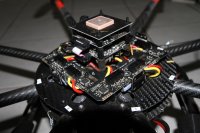
Re the ESC/PDB set up on the Mk - in the Pic attached the +red wire solders to a single point on the PDB, you can see it Just under the Ribbon

Thanks for the part #'s above and there is no problem with supply in Oz in fact they offer a 10% discount for the first order so I guess I will make it a good one (including the Crimpers).

Appreciate your time.
Cheers
Alan
 

Attachments

  • MK Power setup.jpg
    MK Power setup.jpg
    137 KB · Views: 279

jes1111

Active Member
Ouch! Such a silly small pad to attach the incoming power for a heavy-lift okto! I presume the negative is on the underside of the positive (I'm looking at picture of the Octo XL PDB). Tricky - you want to be able to solder two 10AWG wires onto each side - not sure how easy that's going to be - maybe somebody else here has experience. One possible trick to attach two 10AWG straight to the pad is to use some brass tube or thin copper sheet to make a short oval tube - insert the (already tinned) ends of two 10AWG wires into the "tube" and add more solder. This will give you a very robust joint where you have complete control of the exact shape of the tube - shape it to be optimum for subsequent soldering onto the pad.

Anyways - two 10AWG runs from there to the battery (loosely twisting the red/black of each run together is a good idea to reduce radiated interference) - terminate with Powerpoles - swap the battery connectors for Powerpoles. Good to go :)
 

Lifter

Member
Jes1111,

All ordered as per suggestions, our Aussie supplier did not have the crimpers or the Red / Black housings in singular form - only in the bonded type housing so got them all from Power Werx.

Will let you know the results upon receival / testing.

Thanks for your input.
Alan
 

Bartman

Welcome to MultiRotorForums.com!!
Mombasaflash established his worldwide fame by modifying the power board to accept a second set of power wires. Use the tip of an Xacto knife to scrape the paint off of one set of the smaller auxiliary + and - pads to make them the same size as the dedicated power wire pads. This mod allows you to have two independent power attach points and it's something I do standard now on those boards. Be gentle with the scraping and just scratch the surface paint away to make a square large enough to attach the wires.

otherwise about the best you can expect is to put large wires to the one set of pads and then 'Y' out to two sets of power wires.
 

Lifter

Member
Thanks for the info Bart - Not looking forward to the challenge but guess it has to be done - damn terrified the thing is going to drop out of the sky all because of a .50c connector,,

Supose I could just send it to Mombasaflash ..........

Thxs
 

Malcr001

Member
Today and yesterday I replaced all my power cables with 10 AWG wiring this also meant that I had to solder it onto my MK PDB. This was not hard to do although I have never liked the fact that the positive and negative pads are so close. A stray wire to could lead to trouble so double check to the connectors with a multimeter after.

Yesterday was a lot of greif with the EC5 connectors although now that I have learnt a couple of things I can avoid problems in the future.

As jes1111 mentioned dont get solder on the outside of the bullet connector otherwise the connector wont fit into the plug. If you managed to get a lot of solder on the outside you may be able to remove the solder but sometimes its easier just to use another connector and try again. Any small bits of solder I got on the outside I removed with desoldering braid and fine grit sandpaper.

If the wiring is short dont snap on the plastic housing until all soldering is done! One of my plugs housing melted. I didnt realise they have a pretty low melting point.

When soldering on the bullet connector I get a vice, 2 small sheets of wood and place them in between the vice. I then place the bullet connector between the two bits of wood and tighten the vice. This alllow the bullet connector to heat up properly so the heat does not transfer onto the metal vice.

On the EC5 bullet connectors there is also a small holde on the side. Most of the time when soldering the wire onto the connector this is where the solder spills out. I now always make sure when the bullet connector is inbetween the wood panels the hole is blocked by the wood so the solder does not spill out. This reduces a lot less greif trying to remove excess solder on the outside of the connector.

My first try I also managed to fit to the wrong bullet connector in the wrong housing. I did wonder why it seemed so tight lol. So the last lesson is to make sure you are fitting the right housing on the right bullet connectors!
 
Last edited by a moderator:

Top