The vast majority of camera imu's that are sold for model use are compromised by the fact that almost all of the commercially available camera mounts were created without any thought as to how they would be stabilized or how they would manage the inertial loads. That aspect was simply left to the buyer to fathom out. The result of this scenario is that we have a few lame attempts to create a jack of all trades device that must try and cope with many different methods to power the movements along the desired axis. Most use gyros that have a full scale range that is no better than that which the model itself uses. Some mounts have high reduction gears and some use servos in direct drive. Some have very high inertial loads and others less so. What is even more ridiculous is that some try to use the imu on different parts of the camera mount ie. one axis out on the base plate etc. Some will use the servos in feed forward and also in feedback. Proportional and slew. The object of the exercise is to measure the disturbance between what the model does and where level is, so that should tell you where it needs to be mounted. And that point is not where the opposite reaction force of the servo can be seen. Compounded by soft mounting.
About two years ago I had this problem resolved and have since that time played around with various low cost ways to replicate the system. I am pleased to announce that I have joined forces with a team of people in the US who have both the manufacturing capacity to reliably produce such a device and have an extraordinary group of dedicated dev. guys who will now offer this device hopefully in the next few months.
Camera stability actually starts with the model itself as that controls the level at which the camera imu operates. It is rather like a self noise canceling headset where the reverse of the motion wave is fed back into the system to create a straight line. Direct drive high speed motors form the essential part of keeping the latency as minimal as possible.
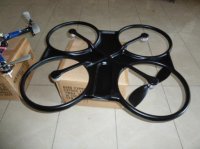
On the subject of the model stability here is a preview of the ROWLAND F1-535 showing the one piece autoclaved carbon base frame. each motor can lift around 2.5 kilos but will probably never need to do that as weight saving is the key to every part of this dedicated system. Camera mount not show for obvious reasons.
View attachment 3212 Shown alongside a flame wheel to compare the size.
") Thanks for keeping me informed.
Thanks for keeping me informed.