5-axis stabilisation

jes1111

Active Member
I've understood from Denny's past posts that "5-axis stabilisation" refers to a gimbal-within-a-gimbal arrangement, whereby the outer (3-axis) gimbal corrects major errors and the inner (2-axis) gimbal cleans up any tiny remaining errors. I was happy with that until tonight when I read this:

The system comprises of a 350mm diameter gimbal containing 5 independent, actively driven axes. 3 for major movements of pitch, yaw and roll and a further 2 axes of pitch and yaw for vibration removal. A total of 8 gyro sensors, 5 accelerometers and 3 magnetometers together with many other position monitoring sensors all work together into a number of digital microprocessors to deliver a state-of-the-art and cost-effective system.
(from http://bradeng.com/product-gyro350)

The part I've highlighted in red - pitch and yaw? vibration removal? Dammit - back to square one! Can anyone explain this?
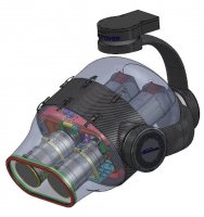
 

PETERJENSEN

New Member
A gimbal within a gimbal is used for applications where high level stabilization is needed, probably mostly military hardware. Often the camera is built into the structure. I believe the second layer of stabilization is done more with various kinds of actuators, some of them might be like a speaker coil. Could this all be pretty heavy? I think so.
 

DennyR

Active Member
It is certainly very heavy, a Cineflex is 67 lbs. The camera and lens is a very small part of that mass. it utilizes a dockable camera body which resides inside the helicopter not the Gimbal.
The Zen is essentially the inner part of a six axis system where the model provides the outer P R and Y the inner axis works to an accuracy of .05 degrees unlike the larger pro size gimbals where the inner axis moves only a few degrees and has a coil type of motor actuator where the camera floats within a magnetic field and can attenuate vibration as well as small movements. it usually has an accuracy of .005 degrees and can utilize very long telephoto lenses. The hollow shaft torque motors come from Axis technology and the gyros are KVH fiber optic usually. There are some stringent patents that cover this inner axis integration which are held by axis technology and John Doyle, however the first person to my knowledge to use thisidea was a British engineer Bob Nettman of Gyron fame. John Doyle is now making the 6 axis Shotover Gimbal in New Zealand. It has been said that the patents run out soon so the shotover may now come to the US.

FWIW the servos that we try to use are also a form of stepper motor. A hi rez. servo like the ones from JR and Hitech have a rez. of 4900 steps over 120 deg.
Attenuating the vibration with Accels. is not a new technology Your iphone has an accelerometer inside which can measure and record vibration levels on your motor arms

The Zen goes through an initialization calibration and it seems to have an auto vibration calibration built in to that program. I think at this moment in time it is quite some way more advanced than anything else outside of mil. spec. stuff. It's operational qualities are very like the use of proper pro size gimbals. Auto object tracking is therefore not far away. DST have had it for some time now.
 
Last edited by a moderator:

jes1111

Active Member
Thanks, Denny.

Revisiting the Shotover site, I found this image of their new 3D version. For the first time I can actually see the axis scheme in one of these 5/6 axis devices - the outer 3 axes (looking remarkably like PH's new gimbals ;)) and the camera(s) mounted within the inner 3-axis mechanism (the red part). The inner mechanism is obviously limited to very small angular movements (since the lens window on the outer casing is fixed).
View attachment 5435
A hi rez. servo like the ones from JR and Hitech have a rez. of 4900 steps over 120 deg.
(Pedant-mode again, sorry ;)) The Hitec HS-M7990TH has an AMS AS5045 Rotary Encoder chip: 4096 positions over 360º (so 0.088º accuracy). I bought some of these for testing but they have a severe jitter problem, even when set up in an antagonistic arrangement. :(

JR claim "5900 steps per 120° of travel" - how do they achieve that? Maybe the encoder is before the output shaft?
 

Attachments

  • 26.jpg
    26.jpg
    80.9 KB · Views: 427

jes1111

Active Member
The best off-the-shelf "direct drive" actuator I can find is this one: http://www.hds.co.jp/HDS_hp_english/english/products/rotary/ac_fha_mini/index.html - 24V pancake servo motor with harmonic drive. The FHA-8C model with 100:1 gearing has a max torque of about 49kg.cm - certainly should be enough for good-sized camera. Unit weighs 400g - so 800g for a 2-axis gimbal, plus controllers at 230g each. Theoretical resolution of 800,000 positions per 360º (if I'm understanding the spec sheet properly) - "sufficient", in other words ;). About US$2000 per axis - actually not too bad when compared against the price of a Zenmuse.
 

R_Lefebvre

Arducopter Developer
Ah, glad I found this thread, as I was recently trying to figure out where the roll axis is on the Cineflex. So is it a similar arrangement as the Shotover one pictured above? I figured that must be the case, then trying to figure out how do they remove the roll from a shot when looking downwards? I think the answer is simply a bunch of geometric calculations being done in the controller. It can be done, but it's a bit complicated.

Wouldn't a Sony CX760 mounted in a standard 3-axis gimbal be a 5 or 6 axis stabilized system? I've seen some really good video coming out of those!
 

DennyR

Active Member
Roll is actually a belt drive system within the inner case and not like the Shotover. If the roll sensors move with the tilt axis then the movements will be the same as seen through the viewfinder.i.e. roll will still look like roll on the stick but it could actually be pan looking straight down.

If you were using the FC outputs on say a PH gimbal, then with the tilt pointing down at 45 deg. you would be seeing a cross axis error from the roll sensor.

The stabilized lens does qualify as a inner axis so why not. I have only seen stab. lenses that correct in pan and tilt but not in roll. I think one of the Canons has electronic roll leveling at the sensor.
 
Last edited by a moderator:

jes1111

Active Member
The Olympus OM-D has a five-axis sensor shift stabilisation system - roll, pitch and yaw rotation plus horizontal and vertical shift. Not sure how well it would work in this application. The camera does 1080/30P.

Roll is actually a belt drive system within the inner case and not like the Shotover. If the roll sensors move with the tilt axis then the movements will be the same as seen through the viewfinder.i.e. roll will still look like roll on the stick but it could actually be pan looking straight down.

If you were using the FC outputs on say a PH gimbal, then with the tilt pointing down at 45 deg. you would be seeing a cross axis error from the roll sensor.
I get what you mean in terms of manual stick movements by the camera op, but I don't fully understand your point. Are you saying the Cineflex (or the Shotover) have additional sensors mounted on the inner axes? i.e. the inner axis compensation is isolated from (and entirely different to) the outer axes?
 

DennyR

Active Member
The Olympus OM-D has a five-axis sensor shift stabilisation system - roll, pitch and yaw rotation plus horizontal and vertical shift. Not sure how well it would work in this application. The camera does 1080/30P.


I get what you mean in terms of manual stick movements by the camera op, but I don't fully understand your point. Are you saying the Cineflex (or the Shotover) have additional sensors mounted on the inner axes? i.e. the inner axis compensation is isolated from (and entirely different to) the outer axes?

It would have to be islolated. How else could it work. It has to sense the actual disturbance that passes the outer system. It is a closely guarded secret how the inner axis works on the latest models but the Zenmuse also has separate sensors for each axis. The orientation of how the extra gyros are placed is a key element on these high end gyro balls. You can find a similar example in the way that a Segway redundancy system works with an array of Silicon Sensing Gyros http://www.siliconsensing.com/segway

SS products are also use by Futaba.

If you consider how fast a loud speaker can change frequency through a coil to move the dish and create sound waves that represent music etc. then you can see how by making a reverse image of any vibration you get a straight line. Like a noise canceling headset. This is the basic principle of how they control vibration
 
Last edited by a moderator:

MombasaFlash

Heli's & Tele's bloke
... Wouldn't a Sony CX760 mounted in a standard 3-axis gimbal be a 5 or 6 axis stabilized system? I've seen some really good video coming out of those!

... The stabilized lens does qualify as a inner axis so why not. I have only seen stab. lenses that correct in pan and tilt but not in roll. I think one of the Canons has electronic roll leveling at the sensor.

So if a ZEN could accommodate a CX760 we would have 8-axis stabilization? How much more could one need? :)
 

DennyR

Active Member
Using the lens as a fine tuning aid would be a far cheaper option than a replicated cineflex system.
 

jes1111

Active Member
Sure - but, as has been proven elsewhere, most camera image stabilisation systems (particularly the in-lens type) cannot deal with "high" frequency vibration. So it is necessary when contemplating using the camera's own stabilisation as the "inner axes" to ensure that "high" frequency vibration doesn't get through to the camera.
 

DennyR

Active Member
Sure, but some are better than others. The Balanced Optical stab. System on the 730 seems to be one that works for some reason. I have not tried it personally.
 

jes1111

Active Member
Slobber! Slobber!

Something I've noticed: on this gimbal (and many others) the roll axis is inside the pitch axis, so the progression is pan > tilt > roll. The Shotover example above, however, goes pan > roll > tilt. (Discounting the inner axes, of course.)

There's a significant difference here in the control scheme, particularly when trying to point at the zenith or nadir. Do these systems compensate for the difference, i.e. behave functionally identically through some electronic wizardry? Would a DP be aware of the differences, or even interested?
 
Last edited by a moderator:

R_Lefebvre

Arducopter Developer
I'm assuming they do some "electronic wizardry" to remap pan>tilt>roll to pan>roll>tilt. It's just a bit of trig, really. Maybe mind boggling to think about, but some math wiz probably figured it out, it is probably just a few lines of code, and the processor cranks through it fast. I'm assuming the "DP" doesn't need to know what is going on, other than the fact that it is roll stabilized, and when you push the stick up, the camera tilts up.
 

jes1111

Active Member
But the problem is "gimbal lock" - with the above gimbal, if you're pointed directly down at the ground your roll axis is now coincident with the pan axis and they both produce the same pan motion. Can they bypass that?
 

R_Lefebvre

Arducopter Developer
But the problem is "gimbal lock" - with the above gimbal, if you're pointed directly down at the ground your roll axis is now coincident with the pan axis and they both produce the same pan motion. Can they bypass that?

I'm trying to get my head around it, but I think it can be done. But it's ugly.

So imagine the aircraft is flying straight ahead, with the camera axis aligned with that direction (ground image is moving top to bottom). Now the aircraft rolls 10°. The "yaw" axis will have to swing 90° so that the "pitch axis" is now roll. The "pitch" axis moves 10° so the camera is facing straight down again. Then the "roll" axis has to turn 90° opposite the "yaw" axis so that the picture is again moving top to bottom.

As I say, it's ugly. If you were hovering, trying to look STRAIGHT down, and the aircraft is making minor pitch and roll movements to maintain position, the "yaw" and "roll" axis will be going crazy trying to compensate.

So I'm not really sure why anybody would build a gimbal this way. The only thing I can think of is that I think it is a stiffer structure. If you compare that structure (and that of the Cineflex), it appears like it's easier to make it stiffer. The "roll" axis is a fully supported circular structure. The yaw is cantilever, but the geometry allows for a nice fat bearing. The "pitch" is doubly supported.

Using the more common method, such as the Shotover and all the Hobby gimbals, you have yaw being cantilever, but it tends to be on a spindly shaft. Then you have roll being either another cantilever, or the "hoop" method, which I'm not a big fan of. And then pitch is doubly supported which is fine.
 

Top