Another power distribution thread

Bartman

Welcome to MultiRotorForums.com!!
Been working on a new helicopter and posted this in the build thread last night but this may be worth its own discussion so here it is. In looking around the internet there are a lot of power distribution boards popping up but they're limited in how much current they can handle.

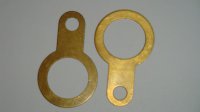
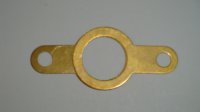
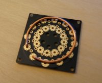
I've got a couple of the available boards on my bench and I'm trying to see what can be done with them but I"m also playing around with a new idea to get power from dual batteries to eight ESC's. What I've done is identified where I want my solder connections to be and have put a loop at each spot. There are also loops to the batteries and four loops for mounting studs to go through. The idea would be to make a positive and negative one of these and then stack them. I've also thought about sliding a short piece of silicone surgical (a.k.a fuel) tubing between each loop for insulation. As each wire is soldered into place, heat shrink could be slid onto the individual loops to insulate them as well.

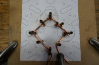
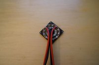
Here's a pic of the first try at this and a pic of it sitting on my frame.

View attachment 4742View attachment 4743

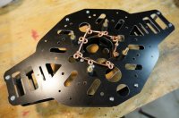
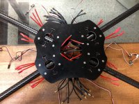
I'm also trying a modification of the Zoltair power board using a short length of 14 AWG solid wire. THe board has holes at each solder pad and the pads extend from the top surface to the bottom. These boards are really versatile and weigh a third of what my two copper loops would weigh. The idea is to solder the wire to each pad around the bottom so it adds to the current capacity of the board.
View attachment 4744

Bart
 

Attachments

  • DSC00141.jpg
    DSC00141.jpg
    131.2 KB · Views: 451
  • DSC00151.jpg
    DSC00151.jpg
    142.3 KB · Views: 417
  • DSC00155.jpg
    DSC00155.jpg
    125.7 KB · Views: 431

Bartman

Welcome to MultiRotorForums.com!!
modified Voltair board with battery leads attached...original weight was about 12g, with the extra wire in place and before the battery leads were attached it's at 22g.

View attachment 4747
 

Attachments

  • DSC00157.jpg
    DSC00157.jpg
    139 KB · Views: 350

yakjock

Member
that seems like a very good & simple idea! I like it.
How many amps do you think it can take with the mod.
 

Kari

Member
Nice idea Bart, but how many amps do you need? Voltair is already very thick and i'm sure it can handle very big octos current without issues. But if you're still worried how about 2 voltair boards?

Kari
 

Bartman

Welcome to MultiRotorForums.com!!
i'm not an electrical engineer. i don't necessarily wish I was but when I start dabbling in worrying about the flow of electrons I have to be very conservative. The VOltair is advertised as having been tested to 72 amps and an Okto with Tiger 2814 motors can theoretically pull 200 total. with the battery in the middle of the board that would be 100 amps in either direction. I'm coming across references to people taking it to higher power levels but I'm not in a position to guess what it would max out at.

I suppose I could put a voltair board in line with some household 110v power and maybe run a table saw or something through it. Power wise, 15 amps of 110 volt power is the same as 110 amps of 15 volt power though I'm not sure how AC compares to DC which is what our batteries produce.

I'll fly the board I modified and I bought an extra to experiment with. It would be interesting and probably good for business if the Voltair designers put it to the test once and for all. It's a very compact and well designed package that could be much more widely adopted if the power rating were better understood.

Bart
 
Last edited by a moderator:

Why even use power distribution? Just solder the wires together and isolate them with thermo retractable, it's way safer. Those boards make absolutely no sense, electrically speaking. Maybe only for esthetic reasons, but are just another thing that can go wrong with high currents, vibrations, poor soldering, etc.
 

Bartman

Welcome to MultiRotorForums.com!!
i built my first Hoverfly quad with a wire harness for power distribution. it was as close as i could get to the minimum wire possible but it was a pain in the you know what to assemble on the frame. the power wires for the FC were left out initially and it was a bigger PITA to pull a joint apart to add two small guage wires into it. i might still go this route but the build i'm doing at the moment is my own challenge to tame the wiring mess that comes with std. ESC's.


View attachment 4752
 

Attachments

  • DSC00163.jpg
    DSC00163.jpg
    139.1 KB · Views: 319
Last edited by a moderator:

Bartman

Welcome to MultiRotorForums.com!!
looking at that picture again it could have been made even more easily by eliminating the #10 wire in the middle and just folding the two sets of battery leads directly over the #14 ESC branch wires. it was originally done by folding and soldering the battery leads over the center #10 wires and then adding the #14 ESC branches. so with about 14" of red and black #12 wire and about 6" of red and black #14 wire you'd have a harness. two esc's go on each of the four branches if anyone wants to try it and the esc's have to have the power wires pointing towards the center.
 

DennyR

Active Member
Why even use power distribution? Just solder the wires together and isolate them with thermo retractable, it's way safer. Those boards make absolutely no sense, electrically speaking. Maybe only for esthetic reasons, but are just another thing that can go wrong with high currents, vibrations, poor soldering, etc.

I Agree, that is by far the best solution. Stopped using BDB's years ago.
 

DucktileMedia

Drone Enthusiast
The board is nice only for convenience of soldering, nothing else. i spent 3 hours staring at my 18 wires to be loomed together and tried soldering to a washer, 4 wires ata time, wire lugs, copper disc. I ended up not being happy with any of them as it was just a royal PITA to get that many wires together in such a small space with such short leads to play with coming from the esc's. Thats why the PDB is so nice. I agree though, just soldering them is worth not having to ever think about that being a weak point. Bart, I have to be honest, I am thinking now about using your solid copper wire idea.

View attachment 4758
 

Attachments

  • photo.jpg
    photo.jpg
    141.8 KB · Views: 322

Bartman

Welcome to MultiRotorForums.com!!
The board is nice only for convenience of soldering, nothing else. i spent 3 hours staring at my 18 wires to be loomed together and tried soldering to a washer, 4 wires ata time, wire lugs, copper disc. I ended up not being happy with any of them as it was just a royal PITA to get that many wires together in such a small space with such short leads to play with coming from the esc's. Thats why the PDB is so nice. I agree though, just soldering them is worth not having to ever think about that being a weak point. Bart, I have to be honest, I am thinking now about using your solid copper wire idea.

View attachment 6435

really? you spent three hours staring at it and I'm a day closer to actually flying and you think it's convenience only?

i like the wire idea too but it was going to be three times heavier than the board. single items don't ncessarily make things too heavy at the end but the tendency to let anything be heavier than it needs to be will show in the end.

fwiw, every MK out there (just about) uses wires soldered to a board of some sort. to date i've never heard of a wire coming off that was properly attached. i did have one wire that came off but it unsoldered itself from the heat that was created when a FET went to hell so the motor was going to stop spinning anyway.

how do you plan to address the possibility of the components on your ESC's from coming off the boards that they are on? or the components on the flight control board? or your camera gimbal control board?
 
Last edited by a moderator:

jrlederer

Member
I am hooked on this thread right now, as coincidentally I went last Friday to the local hardware store to pickup some solid copper conductor (actually used for common grounding in AC installations, or at least that's what the store employeed explained it as...). Great minds think alike? ;) Just to sound even more cliché, then I remember a quote that goes, "some people learn from the mistakes of others...and then there are the 'others'". Not that I think that this method will prove to be a mistake, but since you appear to be a couple days ahead of me in trying this solution out, I feel like it would be best to first hear your analysis before embarking on this sub-project. Thanks, bartman, for taking the time and effort to report back your findings after testing this out; I sincerely appreciate it.

Have a great day and same goes for everyone reading this!
--Jonathan
 

Kari

Member
I have tried few different copperplate/spider/harness ideas but always come back to power boards. I hate the amount of tin AWG10 or 8 wire sucks inside. PDB:s are IMO lightest, easiest and best way to achieve cleanest install with regular esc:s wiring mess. Haven't heard anyone had issues yet well soldered joint coming loose by vibrations, also Voltair boards holes help to this. Also i think Voltair board can handle a lot more that we can ever pull out from our multis under 7kg auw. Even then i think Voltair board would only be warm but not starting to burn or melt solderings. :) I've been just following temps of PDB:s and i have never got even afro board warm at all with Cinestar 6 AUW 5kg, Voltair is at least double as thick so i'm sure we're on the safe side.

Kari
 

jes1111

Active Member
I, too, favour straight soldering over using any kind of PDB. There are two ways to make it easier:

The first is to strip some regular household wire and extract (with pliers) some individual strands of copper. You can then use these to bind individual pre-tinned ends together before adding more heat/solder to fuse everything together. The second is to obtain some small brass or copper tubing and cut some short lengths of it. Then lightly squeeze these pieces so they make an oval shape. Pre-tin your wire ends and insert them into the tubing as required then apply heat and more solder to complete.

Incidentally, one of the reasons that some people think soldering to PDB is easier than soldering wires to themselves is that "correct" soldering technique should always be to heat the part, not the solder with the iron. It should be the heat of the part that melts the solder, not the heat of the iron. Fact is that when soldering to a PCB you can get away with reversing this, allowing the already molten solder to heat the PCB copper, whereas soldering (heavy) wires together by heating only the solder tends to result in a mess :)
 

Bartman

Welcome to MultiRotorForums.com!!
how about this? how about we come up with a scheme to test the voltair board to see what it can really do. if it isn't too complicated or expensive I can offer to do it here but i need help figuring out how to go about doing it. if i had to design something i'd wire it into a 120 volt circuit and run it until the breaker pops at 20 amps. that's ac power though and the highest DC source i have is my car battery charger at 12 volts and 60 amps.

ideas?

PCB's, for what it's worth, are fast and the voltair board is priced to make its use a no-brainer as far as i'm concerned.

but to keep the conversation going here's another idea. take a 14" piece of stranded 12AWG, bare an inch in the middle then fold it in half so you have leads for dual batteries with about 1/2" of doubled over bare wire. Stuff the bare 1/2" stub of the folded end into a #10 ring end terminal, crimp or solder. do the same for the other battery lead. put rings on your esc power wires and bolt them together. if it isn't the simplest and lightest way to do it then come back here and tell us what is. i might have to try it myself actually. it will definitely weigh a fraction of what those big wire rings weigh.
 

jes1111

Active Member
Bolted ring terminals seem like a good idea and they can work well but there are potential issues to watch for: connections need to have the lowest possible resistance (for the lowest possible voltage drop) but ring terminals can introduce surprisingly high resistance unless the surfaces are really clean and really cranked down. And there's the likelihood that the metal will corrode (over a surprisingly short time), thus increasing the resistance even more. Plus there's the fundamental problem of having a bolted connection which is subject to heat/cool cycling together with vibration - it will quickly loosen the connection so you need to check it frequently which mean you can't cover it over which means you have to live with a huge short-circuit hazard.
 

I addressed this problem once before and it worked well but was really overkill for my needs...It would easily carry 100A+. I don't own the MR anymore so unfortunately I cannot take any pictures to show. Purchase 4 brass Banjo washers, 2 for positive and 2 for negative. Seat each Banjo pair on top of each other so that the leg of each Banjo is 180 degrees away from each other. Now using a reasonably high powered soldering iron sweat each pair together. Each Banjo pair can be screw-mounted onto nylon stand-offs/pillars via the banjo legs. The MR loads can be soldered to the relevant Banjo washer pair at any chosen point. Finish it all off by painting it with a thick layer of liquid insulation. Assuming that the soldering is good it will last forever and it ain't ever going to suffer from copper land pattern peel back. I cannot remember the overal weight but it wasn't much more than a typical dis-board. (Brass Banjo washers are used for the glands on steel wire armoured cables and are designed to be robust and to take heavy fault currents). Just another way to help overcome a common problem.
 

Bartman

Welcome to MultiRotorForums.com!!
@jes, i think if the joint was properly lubed and then wrapped, corrosion, resistance, and vibration wouldn't be deal breakers for the idea.

@david, I'm only familiar with banjo fittings used in hydraulic joints like brake lines in cars. Is the banjo washer just a heavy guage brass washer? maybe a link if you have one please?

thanks,
bart
 

Bart, the variety of Banjo washers that I used are very similar to the type used in hydraulic joints just as you have suggested. I've got a couple of the type that I used (not made up as a Dis-ring) lying around somewhere so I'll record their dimensions, take a couple of pics and see if I can find a source for them as they are rather than as part of a gland kit. I'll post it ASAP.


David.
 

Bart, please see the following 2 pics...View attachment 4778View attachment 4779Weight and dimension are...

Individual washer weight : 4grams.
Washer dia.: 29mm.
Washer length : 47mm.
Washer centre hole dia : 20mm.
Washer small hole dia : 6mm.
Washer thickness : 1mm.

When the two washers are overlaid on each other as shown in the pic the small hole-to-small hole dimension is 53mm.

Of course there is sufficient washer body material to drill other holes in the washer 'handle' to suit other requirements.

As I posted earlier this idea worked extremely well for me but I do not know of anyone else that has experimented with something like this. Many MR frames now come with a built-in dis-board and that is possibly a way of things to come.

The washers are often referred to as earth tags and are manufactured in many sizes. Please see the following sites in the UK...

http://www.earthtags.co.uk/
http://www.prysmian.co.uk/export/sites/prysmian-enGB/attach/pdf/cable_glands/Gland_Accessories/Earthtags.pdf
http://www.cablesystems.co.uk/products/38/hawke-earth-tags.html


Attachments

  • DSC01417.jpg
    DSC01417.jpg
    95.5 KB · Views: 301
  • DSC01418.jpg
    DSC01418.jpg
    86.7 KB · Views: 269

Top