You are using an out of date browser. It may not display this or other websites correctly.
You should upgrade or use an alternative browser.
You should upgrade or use an alternative browser.
Mikrokopter Bad roll gyro
- Thread starter J.T.
- Start date
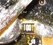
Ah the great 000 jumper coverup. 
When and where did you buy this board?
See those little parts that say 000? You got a faulty board that MK so kindly pushed out to people some time last year.
There were suppose to be large solder pads on the boards. Somehow they got left off and MK decided to use brittle 000 jumpers as a fix.
It's only a matter of time before they crack and the gyro fails. I hope the damage wasn't significant.
Here's the thread where the problem first came to light:
http://forum.mikrokopter.de/topic-18336-7.html
Also see pics below.
Attachments
OMG, this is so interesting. So I've a bodge up £350.00 FC. Thanks so much for your input guys. I don't suppose I stand a chance of getting it changed. Does the FC have a 12 month warranty? It's so typical, Iv'e got my first paying AP job in a couple of weeks aswell.
You'd be lucky to get a 12 second warranty from MK. If I'm not mistaken I think Holger did say he would repair these boards for free though.
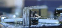
To fix you would need to desolder those 000 jumpers and toss them out. Then replace them with a piece of wire. Reflow the other existing solder joints on both boards (top and bottom). Then epoxy the boards down so they can't wiggle around.
Also look at that resistor next to C56. If it doesn't have two pads, then that needs to be fixed also.
BTW, It's not a 100% guarantee the the above is your problem but it is the most likely problem by a long shot.
Droider
Drone Enthusiast
Thats bad.. bad ,bad.. Ring him, Holgar that is. At least you may get some satisfaction.
On a side note Geoff at www.quadcopters.co.uk has just got the UK MK dealership.
If you need out quick he is just about to place an order.. If you are desperate I have a stock of MK stuff including a FC 2.1
Dave
On a side note Geoff at www.quadcopters.co.uk has just got the UK MK dealership.
If you need out quick he is just about to place an order.. If you are desperate I have a stock of MK stuff including a FC 2.1
Dave
Droider
Drone Enthusiast
Side note to that.. Geoff is waiting on his webmaster to update the site. if you need out bell him on the number on his site.. VERY helpful chap. Anyone in the UK how wants out MR related should give him a bell if it aint on his site. He is growing fast on what he offers and is getting more arrangements weekly with major suppliers so give him a call.. he showed me a really nice new folding FPV quad yesterday for not silly money LED's included and pan ant tilt FPV camera mount..
Dave
Dave
I have one of those boards also, has over 1000 minutes of flight time on it last time I checked in MKtool. When I head about the 000 resistor bodge I did the fixes as Mr Crash suggests and it hasn't had an issue. If I remember correctly I used little pieces of solder wick to replace the 000 block and then soldered the snot out of all the connection points, those gyro boards aren't going anywhere now!
Ken
Ken
Mr Ken, do you happen to have a picture of your fix?
Don't know if I do or not, I'll have to check my digital photo repository. The board is currently buried in the bowels of the Droidworx Hexa heavy lifter (hows that for trust!) so not much chance of taking one until the next time I have opportunity to be under the hood taking the boards off the stack.
Ken
Ok, I think I found one! I'm pretty sure this is it and as you can see there's just big blobs of solder where the 000s used to be as whatever I used (I'm thinking now it was pieces of cut off resistor leads and not solder wick) I encased in solder as well as beefing up the existing solder connections. This is also the same board that popped the power input diode two flights after I swapped the servo Recom to one of Ziggy's 6 volt replacements so it's been repaired and had some work done on it. I recall Ziggy making a comment about all the additional solder work that had been done on it. Doesn't matter to me what it looks like as long as its reliable and works! Oh, and BTW, I did add a couple drops of thick CA to where the boards join so I hope I never have to replace one of those suckers...

Last edited by a moderator:
Dave ,
I'm being ignored by HiSystems, surprise, surprise.
As I said I've got my first paying AP job in a fortnight and really need a reliable stable quad for the job. Is the FC 2.1 new and how much do you want for it.
I'm so pleased we now have a UK dealership for our "stuff".
All the best,
Jim.
PS. Your PM inbox is full.
Bartman
Welcome to MultiRotorForums.com!!
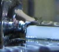
just so I understand this correctly, in the third picture of post #3, did they use the 000 resistors as a shim under the gyro or as a jumper to pull power to the base of the gyro? if it's the latter then Ken is replacing the resistor with a length of hard wire and just globbing over it with solder to hold it all together? i've never really understood what this issue was about, other than poor manufacturing standards and customer service, but now it seems more clear looking at JT's pics.
thanks,
bart
thanks,
bart
They are essentially using those 000 ceramic jumpers to help mount the gyro board to the main FC board as well as conduct signals. Those parts are not intended to be structural, they are made to be soldered to a circuit board on both sides.
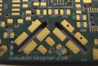
Look at the pic below of a good board. Do you see the 8 big pads that are intended to hold a large amount of solder to mount the smaller boards? Somehow they were left off in that batch.
View attachment 540
Thinking that you can replace those big pads with little ceramic jumpers is just plain stooopid. Those faulty boards should have never been sold to the public and the people at MK should have known that there would be problems.
It doesn't take a Mechanical Engineer to know it's not smart to use glass hinges on a car door.