Son of Okto

Bartman

Welcome to MultiRotorForums.com!!
I've been kicking around ideas for a one-off custom copter and rather than put it together in my basement in secrecy I've decided to open it up for everyone's input.
In laying it out the way I have I'm trying to do a few things. First is build in lots of redundancy so that I can use it for my aerial photo business and not worry about canceling appointments and having it crash in front of customers because of minor malfunctions. Second, I'd like to reduce airframe vibration by optimizing the layout. The camera mount shouldn't be the last hope for vibration isolation but that's where things have gone. Have you seen the sky rover? They should call it the Sky Grommet for all the rubber they've got built into it. Lastly, I'd like to use fixed pitch helicopter rotor blades cut down to maybe a sixteen inch diameter with gear reduction to slow down rotation (maybe improve rotor efficiency while eliminating some high freq vibration).
I'm calling it a Dual-Pac Quad because each arm of the quad will have two motors driving one rotor through gear reduction.

As of now I've been considering using the MK flight control board but I'm open to suggestions. MK is what I know so that's what I planned. I also need suggestions for ESC's. I've been taught that MK boards need MK ESC's but I'm guessing we've moved beyond that. Any help would be appreciated.

Another thing I want to incorporate is a free hanging camera mount. In my mind I've got a picture of a camera mount hung from the quad with a CV joint or universal joint so the quad can tilt for control but the camera mount will still hang down. I think this will eliminate some of the jitters that show up in video and give the mount a ride more like a helicopter does. the joint would have to prevent rotation (it wouldn't be completely free hanging) and there would have to be three or four point shock absorbtion around the joint to keep it from swinging. Lastly the mount will have to have it's own gyro stabilization since it will have some degree of freedom from the copter.

sound easy enough? i'm ready to get to work.

Bart
 

Bartman

Welcome to MultiRotorForums.com!!
the layout i've been planning will have round carbon fiber arms through a round aluminum tube body. at the top of the body there will be a cap and on top of the cap will be the fc board, navi board, i2c isolator board, and gps receiver. in the center of the cap will be a hole for a #10 threaded rod. maybe a #10 will be too big, maybe it will be too small but that can be worked out later. the construction of the quad's center body will be like a trophy or lamp where the rod holds the different layers together. on top will be the cap, below that will be a 2" (maybe larger, probably smaller) diameter aluminum section where the arms will go through. there will probably be a short section of aluminum tube (1/2" ID) in each direction for the CF arms to plug into. ESC's will go out on the arms and everything will be modular so repairs and preventative maintenance can be done without taking the whole central body apart. I'd like to have the props under the arms so the wash from the props isn't beating on the arms themselves and causing vibration. lastly, in the pursuit of minimum airframe vibration, the left and right arms will be at one level and the front/back will be an inch or so above or below the others. prop tips throw wash out laterally and having all the props in the same plane with their tips passing just fractions of an inch away is likely contributing to airframe vibration.
bart
 

Bartman

Welcome to MultiRotorForums.com!!
continuing with the layout below the aluminum body there will be another cap. maybe you can call it a plate but the rod will pass below that and either terminate or go right into the flex joint for the camera mount. the bottom plate will have to flare out so that there can be mounting points for landing gear and for the flex joint's shock absorbers. this might also be a good place to have battery mounting plates. a goal in all of this is to have as few protrusions into the props' airflow as possible and wherever possible smooth shapes are preferred. it might even be worthwhile to have a cap of some sort over the camera mount so that airflow won't meet up with an open frame to beat on as it passes by.
is the picture any clearer?
bart
 

Bartman

Welcome to MultiRotorForums.com!!
For my Son-of-Okto build I'm going to double up motors to get redundancy while still having a quad layout. In other words, if a motor fails I hope I can maintain controlled flight and get back to the ground without crashing or hitting anything. I bought metal gears to use as part of a test stand but I'd like to go with plastic gears on the actual quad to save weight. I'm not familiar enough with rc helicopters where plastic gears are common. Would plastic gears be enough for a set-up like this? I just ordered aluminum for the main body/hub. It should be here next week and I can start building. It's looking like 5/8" CF arms and about 14" from hub to rotor shaft.
Thanks,
Bart
 

RTRyder

Merlin of Multirotors
For my Son-of-Okto build I'm going to double up motors to get redundancy while still having a quad layout. In other words, if a motor fails I hope I can maintain controlled flight and get back to the ground without crashing or hitting anything. I bought metal gears to use as part of a test stand but I'd like to go with plastic gears on the actual quad to save weight. I'm not familiar enough with rc helicopters where plastic gears are common. Would plastic gears be enough for a set-up like this? I just ordered aluminum for the main body/hub. It should be here next week and I can start building. It's looking like 5/8" CF arms and about 14" from hub to rotor shaft.
Thanks,
Bart

Wow, this one sounds BIG and more than a little complex! I'm not quite so ambitious, or rather it's too darn cold for me out in the garage this time of year to attempt a project of this scale, maybe in a couple months when things warm up.

Anyway, as far as plastic gears go, yes they are used quite a bit on helis with varying degrees of success. Both of my gassers have plastic main gears though the plastic is Delrin and quite thick to survive the torque produced by a 23cc two stoke engine. The little Trex 450 also uses plastic main gears though the pinions are metal, generally brass, occasionally steel. End result is that a crash resulting in a quick stop of the rotor blades almost always strips the teeth off the main gear leaving the metal pinion untouched. In your application you might get away with plastic all around provided there's some strength and thickness to them. The bigger problem may be finding off the shelf gears that have the right ratio for what you want to do.

Ken
 

Bartman

Welcome to MultiRotorForums.com!!
Ken,
Thanks for the reply. I spent a lot of time trying to find gears to do what I'm looking for. I also had to try to match up the motor kv value to the gears. I ended up with steel monster truck gears but they're pretty heavy and all the heli's seem to use plastic so I thought I'd ask. You're answer means I'll try to find a plastic main gear and brass pinions for the actual quad parts.
I bought some turnigy motors for the test stand because they're cheap but I hope someone will chime in with guidance as to what motor's/esc's are compatible with the MK FC board. If I have to I'll tailor everything to the bigger MK motors and ver 2.0 BL controllers but I'd really like to expand my horizons regarding hardware.
Bart
 

Bartman

Welcome to MultiRotorForums.com!!
I received some materials in the mail yesterday but an ear infection has me sidelined. Maybe if the kids get to bed early I'll work on it a little tonight.
Bart
 

Bartman

Welcome to MultiRotorForums.com!!
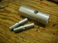
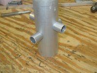
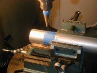
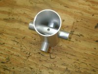
I had a chance to get some work done tonight on the main body of the quad I've named "Son of Okto". The 2" aluminum body will be cut to length after the sockets for the arms are welded into place. If anyone knows someone who is an expert Tig welder please shoot me their number and I'll send the parts to them. Otherwise I'll have to find someone local.
I haven't decided if I'll run the wires in the arms or outside of them so I put slots in the arm sockets for the wires to pop out internally if I happen to go that route. There are also holes for a central rod to run vertically through the arms. I'm new to doing build threads so sorry if I get too carried away with the explanations.
I'll try to spend some time working out details of the drivetrain and I should order 5/8" CF tubing for the arms as well.
This'll be a slow build, really slow.
Bart
 

Attachments

  • P1010184.jpg
    P1010184.jpg
    142.5 KB · Views: 415
  • P1010185.jpg
    P1010185.jpg
    139.6 KB · Views: 285
  • P1010181.jpg
    P1010181.jpg
    141.8 KB · Views: 290
  • P1010186.jpg
    P1010186.jpg
    143.9 KB · Views: 262


Top