XAircraft X650 build thread

Bartman

Welcome to MultiRotorForums.com!!
Well, what else is a guy to do when he's boarded into his house week after week due to record snowfalls? Buy a quad? Exactly!
I just ordered an XAircraft X650 quad because A. I need something to fly every night after dinner B. My soon-to-be 7 yr old son needs something to fly every night after dinner and C. I need a less expensive multi-rotor to carry a less expensive camera for lower paying AP work involving residential real estate.
I'm expecting to have it by the end of the week so expect some progress here when that happens.
:)
 

Bartman

Welcome to MultiRotorForums.com!!
The box arrived today with the evening mail. Our ice storm gave way to rain around midday and now heavy wind as the sun set. With the kids upstairs getting ready for bed I figured I'd dig in and see what I've got to work with.
This post will echo pretty closely what matrosek already posted in XaircraftUSA's vendor area. The packaging is well organized and everything is either in a cardboard box or in heavy zip-lock bags. The instruction manual is printed clearly with good assembly diagrams and all the part numbers, including screws, washers, etc. are reprinted on the actual zip lock bag labels.
 

Attachments

  • P1010195.jpg
    P1010195.jpg
    144.7 KB · Views: 347
  • P1010191.jpg
    P1010191.jpg
    140.7 KB · Views: 284
  • P1010196.jpg
    P1010196.jpg
    140.3 KB · Views: 281
  • P1010194.jpg
    P1010194.jpg
    141.3 KB · Views: 293
  • P1010193.jpg
    P1010193.jpg
    132.8 KB · Views: 394

Bartman

Welcome to MultiRotorForums.com!!
The assembly diagrams show screws and stuff by part number. The part numbers are on the bag labels along with the metric sizes.
Everything is installed by threading a screw directly into the part you're assembling. There aren't any nylon insert lock nuts so a thread locker like Locktite is absolutely necessary on the ends of the screws.
I started by mounting the motors to the motor mounts. It seemed like the obvious thing to do, however, I would recommend putting the motor mounts onto the arms first and installing the M1006 screws BEFORE pushing the wires through and mounting the motors. The reason is that the motor wires get in the way while installing the M1006 screws and getting the M1006 screws past the wires turned out to be a little more of an effort than I expected.
That's it for tonight. I've got the motors on the mounts and the mounts on the arms. Everything is locktited (lockedtite?) in place so we're moving onto the body and the electronics in the morning.
 

Attachments

  • P1010202.jpg
    P1010202.jpg
    133.3 KB · Views: 415
  • P1010200.jpg
    P1010200.jpg
    137.1 KB · Views: 432
  • P1010204.jpg
    P1010204.jpg
    139.7 KB · Views: 269
  • P1010203.jpg
    P1010203.jpg
    143.8 KB · Views: 341


Bartman

Welcome to MultiRotorForums.com!!
Spent some time on the frame while sipping my midday tea. Following the instructions got me through the steps just fine. The instruction manual doesn't say what to do in what order, it diagrams each step by showing the parts to be assembled in an exploded view with cautions and notes in boxes on the page.
For page 7 the only thing I'd point out is that, for the '+' configuration, four of the bottom screws will have to be removed to mount the landing gear later in the build. Those four screws probably shouldn't get any locktite at this point so they can be easily removed later.
Other than that, the parts go together as quickly as you can dab locktite and turn an allen wrench.
 

Attachments

  • P1010208.jpg
    P1010208.jpg
    141.9 KB · Views: 258
  • P1010206.jpg
    P1010206.jpg
    140.8 KB · Views: 272

Bartman

Welcome to MultiRotorForums.com!!
The arms went in fine and everything's all tightened up. You may notice I installed the arms in a nonstandard fashion with the front and rear arms having the props above the arms and the side arms having the props below. I did this for a few different reasons and mostly to try to reduce airframe vibration.
First, I don't love having the props all turning in the same plane with their tips passing so closely from each other. This isn't as big a problem on quads as it is on 6 or 8 rotor multi's. Props don't just throw wash downward, they also throw wash off the tips into the paths of other rotors. This adds to vibration so I thought I'd try to reduce that source by having the props turn a bit of a distance away from each other.
Second, propwash being thrown downward across the arms creates vibration. I suspect the round arms of the XAircraft design will reduce that effect but I think putting the props below the arms will come close to eliminating it.
Third, the Xaircraft design is plug-and-play instead of solder-and-play which will make it easy to disassemble it and change the configuration if my experiment fails.

Disclaimer: If this is your first multi rotor helicopter i suggest you build it according to the plans and get some time on the sticks before trying different things. End of disclaimer. :)
 

Attachments

  • P1010211.jpg
    P1010211.jpg
    140.7 KB · Views: 353
  • P1010210.jpg
    P1010210.jpg
    136.2 KB · Views: 285


Bartman

Welcome to MultiRotorForums.com!!
Current US prices are at Xaircraftusa.com. I bought the fiberglass arms version and it was $600 shipped. Adding GPS and altitude hold features later will add another $300 or so.
Bart
 

Bartman

Welcome to MultiRotorForums.com!!
Forunately for me, I'm on standby duty all week and so far I'm doing a lot of standing-by and not so much duty so I'm able to keep tweaking the website and building the X650.

Edit made after first flight: There's an important detail to point out before you start assembling the electronics stack. The kit includes four plastic screws (M3x22mm) that are inserted from underneath and secured in place with four plastic nuts before the cooling fan is slid down onto them. DO NOT USE THE PLASTIC SCREWS. They quickly wear against the lower frame plate and FC PCB and fail allowing the whole stack to float independent of the quad. I was told of this design flaw but figured I could get in a quick test flight before pulling it apart to make the modification. The screws failed less than a minute into the first flight! When they failed the quad oscillated rapidly before flipping over and diving head (dome?) first into the snow.

REPLACE the plastic screws with steel ones, slide some heat shrink tubing over the screws close to the head where they pass through the lower frame plate so they won't chafe the frame and then put steel nuts onto the screws to hold them in place. There is still a failure mode that will protect the stack and that is the plastic stand-offs that will go onto the steel screws. The plastic can break if you bang it in dome side down if that's even important really. Skip ahead to post #32 to see pics of how I mounted the electronics stack after the crash.


Also worth mentioning, put the four wire comm cable into the Link port of the flight control and the six wire data cable into the correct port of the flight control before assembling the stack since it is difficult to see if they are fully plugged in once the stack is assembled.

Now, back to the original post.

To start mounting the electronics you first have to mount the center thruster, um....er.....i mean the cooling fan. (don't use the plastic studs) To do so there are four screws that get installed from the underside of the bottom plate and they get nuts screwed on to keep them in place. From there the cooling fan gets lowered onto the studs and the four little barrel spacers get put on the studs last. After that you just follow the directions and put the components in place making sure everything is installed properly referenced to Forward which, in my case is the arm with the prop on it. When installing the first board above the cooling fan you have to decide where to route the power wires. I chose to put it straight down through the square hole in the frame directly under where the wire extends off the board. I guess I'll learn later if that was a good decision or not. If it wasn't it will be easy enough to change to some other routing.
 

Attachments

  • P1010212.jpg
    P1010212.jpg
    148.9 KB · Views: 308
  • P1010214.jpg
    P1010214.jpg
    146.7 KB · Views: 317
  • P1010215.jpg
    P1010215.jpg
    147 KB · Views: 315
  • P1010213.jpg
    P1010213.jpg
    148.1 KB · Views: 333

Bartman

Welcome to MultiRotorForums.com!!
I'm almost done with the landing gear and I'll post pictures in a minute but first I have to air a little gripe I have with XAircraftUSA's owner, Jeff Wright. When I called Jeff to talk to him about something unrelated to buying a quad, I happened to mention I was looking for a beater project to make the subject of a build thread and to fly around in the yard without regards for the money I spent on it. Well, Jeff starts to tell me about the X650 and how it's reasonably priced and how it'll haul a gopro or a point-and-shoot and before we're off the phone I've pretty much got it in my head that it'll be a good beater for the money. I'm thinking maybe I can use it for paying jobs when I don't need the full Okto and risk crashing it.
What Jeff didn't tell me is that the thing is actually a really nicely designed aircraft and that it's hardly a beater. I wouldn't be surprised if it gets an award for design. Imagine you want to build a quad and your uncle happens to own a fully equipped CNC machine shop, that's the picture I imagine when I'm thinking how this thing came about.
So Mr. Jeff, the X650 is too nice to be called a beater, not that that's a bad thing.;)
 

Bartman

Welcome to MultiRotorForums.com!!
Moving right along, here are a few pics of the landing gear going together. Nothing tricky to it but the pics aren't that good since the black fittings get lost in the pic against the black legs. To mount the gear assembly you have to remove four of the small screws from the bottom of the frame and replace them with longer ones.
All of the little fittings that you see in the pics are aluminum.
 

Attachments

  • P1010216.jpg
    P1010216.jpg
    131.6 KB · Views: 387
  • P1010220.jpg
    P1010220.jpg
    143.8 KB · Views: 310
  • P1010219.jpg
    P1010219.jpg
    144.5 KB · Views: 274
  • P1010218.jpg
    P1010218.jpg
    143.3 KB · Views: 289

Bartman

Welcome to MultiRotorForums.com!!
I hit a snag last night while trying to get the props mounted. After balancing them I screwed the first one onto the motor shaft. The motor shafts are threaded and there's a threaded brass insert in the prop. The problem comes from the fact that the motor shaft isn't threaded all the way down to where the shaft exits the top of the motor. Every prop I've ever mounted has been mashed up against a surface of some sort so while mounting the first prop I turned it until it started to feel snug and, seeing it wasn't all the way down, I kept turning, and turning, and turning until I realized something wasn't right. Removing the prop I saw that I cracked the prop hub and messed up the brass threads a little.
There aren't any instructions explaining how the props are to be mounted so I called Mr. XAircraftUSA himself, Jeffery Wright. He explained that the props are to be screwed on to the point that they bottom out on the threads and that's it. A nut goes on after the prop is in place and that gets mashed against the prop so the whole thing is locked in place on the shaft. He admits it's not the greatest design in the world and that I wasn't the first to mess it up. He's also working on a spacer of some sort that the prop can go against so mashers like myself won't be able to do anymore damage.
 

Cabe

Member
I see you too come from the "FT" or "fuuuuuuuuuuu...................................lly tight" world of spanner bashers.
 

Bartman

Welcome to MultiRotorForums.com!!
yes, i have been known to overtighten a fastener or two. my granddaddy would be shaking his head if he could see the cracked prop hub. :eek:
 

Bartman

Welcome to MultiRotorForums.com!!
Moving right along, I woke up early this morning and had some time to get things back on track. It was mentioned in another thread that the 'x' configuration is better if you intend to mount a camera. I've been building mine with the '+' configuration but decided early this morning shortly before waking that I'd swap it around and go with the 'x' set up. To further make this build thread worthwhile, I opted to make the swap BEFORE my morning coffee. That's right, disassembly and reassembly in the early AM without coffee.
All in all it only took about 45 minutes. I first removed the landing gear (4 bolts) and the took my inverted motors and made them upright (4 bolts). Next came the removal of the electronic components (4 nuts, 8 threaded stand-offs, and 4 more nuts).
The instruction manual includes complete instructions for building the '+' and 'x' configs so once I had the 'x' pages in front of me it all went right back together.

Worth mentioning is the fact that the labels on the flight controller and the AHRS-S face in opposite directions so when you're stacking them up in the center of the quad, don't just assume both labels face in the same direction.

I also took the fan wire and bundled it up and zip-tied it to the frame.
 

Attachments

  • p1010222.jpg
    p1010222.jpg
    138.1 KB · Views: 274
  • P1010223.jpg
    P1010223.jpg
    144.3 KB · Views: 267

matwelli

Member
re-prop mounts - how difficult would it be to cut off the threaded part and install "normal" 3.0mm prop adaptors / that way "off-the-shelf" props could be used.

Re-the fan - is this for ESC cooling, hadent seen one used on a multicopter before, interesting to see how well it works, like teh idea of having the ESC's tucked away out of sight
 

Bartman

Welcome to MultiRotorForums.com!!
re-prop mounts - how difficult would it be to cut off the threaded part and install "normal" 3.0mm prop adaptors / that way "off-the-shelf" props could be used.
I suppose a prop adapter could be slid right over the threaded shaft but there's only a mm or two of solid shaft below the threaded section. That's what threw me off, the prop almost looks bottomed on the shaft so you keep turning (and turning) only to find that you're damaging it. I think a spacer of some sort is needed for the prop to bottom against.

Re-the fan - is this for ESC cooling, hadent seen one used on a multicopter before, interesting to see how well it works, like teh idea of having the ESC's tucked away out of sight
the fan is for cooling of the component stack, yup. it's a nice detail since there is a lot of current flowing and most of the time (in my case at least) there will be minimal airflow to aid cooling.

Now back to the regularly scheduled programming!
Bart
 

Bartman

Welcome to MultiRotorForums.com!!
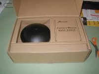
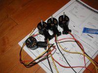
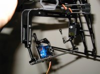
Yesterday morning I spent some time assembling the camera mount. In preparing to build the X650 I overlooked the fact that I'd need two servos for the mount but I was able to find in my collection of stuff a new/old Tower Hobbies TS-11 servo for the nick function and a Hitec HS-55 for the shutter. The shutter release is a mechanical system comprising a servo with an arm that can be adjusted to reach up and over the camera to rest a nub on the release button. When you throw the switch the servo moves the arm which presses the button. I'm using my wife's Panasonic TZ3 and I was able to program the burst function to take five pics at a rather lazy continuous pace for each press of the button. That'll work for me.
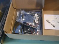
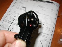
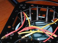
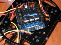
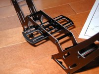
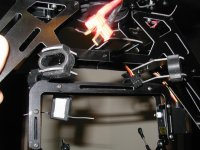
The attached pictures show the nick servo and the little aluminum plates I had to install to have the servo stay tightly in its spot. The holes in the servo mounting tabs were way bigger than the tiny screw that holds it in and there's no room for grommets and such so I just cut and drilled some scrap aluminum I had laying (lieing? :confused:
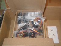
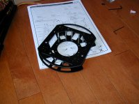
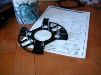
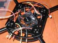
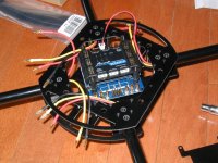
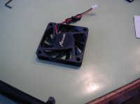
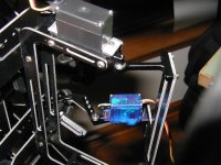
) around. The other two pics show the vibration isolating rubber pieces that the whole mount hangs on as well as the servos that control the mount. I didn't connect the servos to the mount because I want to get the quad and radio fired up before I lock anything in position.
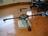
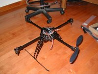
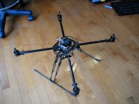
I've got to get the quad configured before I do anything else. It comes from the factory set to operate in the '+' configuration with 3S packs but I've got it set up as an 'x' and I bought 4S packs for it. There's a simple file install that has to be done but I can't get the quad to talk to my computer and it's possibly due to my laptop being run with Windows XP. We're working on it.
Other stuff done today involved swapping out battery connectors to female Deans Ultra since the copter comes from the factory with a male Deans Ultra. I also had to swap out all of the charging/balancing taps on the packs for my Cellpro chargers.
I'll update this in a day or two when I have the software updated and the replacement props installed. It's ready to go and I'm just waiting on those two things.
Happy coptering.
Bart
 

Attachments

  • P1010228.jpg
    P1010228.jpg
    133 KB · Views: 299
  • P1010227.jpg
    P1010227.jpg
    138.7 KB · Views: 301
  • P1010226.jpg
    P1010226.jpg
    135.4 KB · Views: 317

Bartman

Welcome to MultiRotorForums.com!!
One more thing, the two pivot points for 'nick' have to be disassembled and locktite needs to be applied to the two screws before reinstalling them. The factory doesn't do this and it's likely it would come apart if locktite weren't applied.
Bart
 

Top