Took apart my ebay steal the tarot T810. Check out the pics.

photojunky

Member
Today I took apart my Tarot T810. Good thing I did because I found some exposed wires hidden in the frame and an ESC wire that was sliced. If the thing ever got off the ground in the condition it was in it probably would have fallen out of the sky at some point. Everything else looks good (frame) for the most part but there was some weird sticky grease like paste I could not identify all over the screws and bushings. I'm sure it serves a purpose.

I ordered a replacement ESC, banana connectors, and will soon order the battery, flight controller and what ever else it needs to get it off the ground. I'm looking forward to soldering the new wire harness.
Tarot1.jpg
Tarot2.jpg
Tarot3.jpg
tarot4.jpg
Tarot5.jpg
Tarot6.jpg


Any suggestions are welcome.
 

Attachments

  • Tarot1.jpg
    Tarot1.jpg
    331.4 KB · Views: 1,817
  • Tarot2.jpg
    Tarot2.jpg
    402.6 KB · Views: 1,792
  • Tarot3.jpg
    Tarot3.jpg
    401.5 KB · Views: 1,779
  • tarot4.jpg
    tarot4.jpg
    484.9 KB · Views: 1,595
  • Tarot5.jpg
    Tarot5.jpg
    420.1 KB · Views: 1,655
  • Tarot6.jpg
    Tarot6.jpg
    290.7 KB · Views: 1,617

Alwil

Member
That grease is something else! It is used for the arm bearings (bushings) and wants to get
all over everything. I tried to use q tips to wipe off the excess but it just smeared it. You did
well to tear it down and find the wiring problems. It looks like someone was in a hurry and
eventually it would have shown up.
 

violetwolf

Member
Don't you have a thread on this build already PJ? You should try to keep it all in one thread so it's easier to track progress and give input ;)
 

photojunky

Member
Yes there is, and I was thinking about that when I posted this one. Sorry about that. From now on I will only use this thread for the updates. Deal?

Today I should be getting the banana plugs, and tomorrow possibly the battery. I am going to bench test everything before I put it back together.

I like the idea of keeping the ESC's on the outside. That way you can monitor their temperatur. Also, I noticed most of the frayed wire was where the wire entered the tubing. It seemed to rub through the insulation even though there were protective grommets. I am not sure if it is advantageous to keep the wires in the tubes in the first place. Sure they will be protected from the elements, but if they go bad you will never know until failure. Anyway, I will keep you updated.
 

Alwil

Member
Those grommets kept working loose on mine- ended up putting them in place with
a dot of glue to hold them. I also inserted the wires in the flex loom which runs the entire
length of the boom and out the grommets. So far so good.
 

violetwolf

Member
Yes there is, and I was thinking about that when I posted this one. Sorry about that. From now on I will only use this thread for the updates. Deal?

Can we consolidate the two threads (ask the mods), or copy paste the posts in this thread into the other and delete this one. If possible so the input so far isn't lost

We should always bear in mind these type of threads are a resource to others, future builders, newbs etc.

Sorry I'm a pain in the a** lol
 
Last edited:

Old Man

Active Member
Pay attention to the wiring if placing the ESC's on the arms. You can end up making a non folding hex in very short order. Don't ask how I know...
 

I had a hell of a time capturing everything together to tighten up the screws with my tarot 960. Here's the video I made.


Old Man

Active Member
I try to not remember that experience. It works the same with the old 810 except the motor mount halves would fully separate. Perhaps helpful for someone in the future, I found laying the frame center of a piece of soft foam would allow everything coming up from underneath to remain in place as the frame was moved around. However, judicious use of clear silicone assured screws stayed were I wanted them and made the frame less "noisy" after a lot of flights.
 

photojunky

Member
Great video John, I am a little behind with this project. I bought a servo tester but unfortunately is does not work with a 22 volt battery but the new one should be here Tuesday. In the mean time I am going to start soldering the wire harness. I am unsure how many additional leads I will need other than the 6 positives and negatives for the motors so I will not shrink wrap the two battery wires till I figure it out. Led lights, PMU etc.....
Judging from the two previous posts, John's & Old man's, reassembling the frame may not be as fun as I had hoped. Thanks for your help, and I will soon post the updates on this thread.
 

photojunky

Member
This may be a dumb question, but does this thing have a front? Or is that up to the direction my flight controller is aiming?
 

violetwolf

Member
I try to not remember that experience.
No, no , no , no, no.. (sitting in corner rocking back and forth sucking thumb.)

I found laying the frame center of a piece of soft foam would allow everything coming up from underneath to remain in place as the frame was moved around. However, judicious use of clear silicone assured screws stayed were I wanted them and made the frame less "noisy" after a lot of flights.

I think I came up with a similar system using masking tape to hold the screws in place while laying the plate on a pillow. A mental and dexterity exercise for sure.
 

The two non folding arms are right and left, I think it doesn't matter after that. You only need one set of power leads for accessory's, after that you can just branch off of that although two is better cause you can dedicate one for the PMU and then use the second for everything else. I'm a fan of the little voltage regulators. I bought one from hobby king. I feed my battery leads to it then it gives me two (or more) 12 VDC outputs for lights, gimbal, FPV etc.


Old Man

Active Member
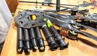
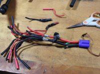
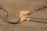
Regarding wires exiting the booms inside the frame. I've had the same issue with wire chafing at the exit opening others have experienced. After becoming fed up with trying to re-fit those grommets I also elected to use some braided sleeve at the exits to protect the wires, but limited the amount of sleeve to just a few inches to the inside of the tube and enough on the other side to reach the PDB. A little tape and a small zip tie on the end inside the boom keeps it fixed.

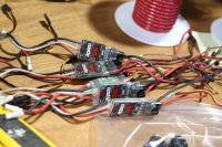
As for accessory power taps, don't make the mistake I made and set up too many. A bunch of loose wires looks bad and is dead weight. After all the work was done I looked back and decided only two accessory taps were necessary, one for 5v and a second for 12v, each having an independent voltage regulator. You can add numerous accessories later to either power buss if only two things are done. One, limit the amount of current that will be drawn through the regulator and, two, construct a power expansion strip of your preference that allows for easy connect/disconnect options. A simple JST breadboard or similar could be made for each voltage lead that possessed as many accessory connection points as your heart desired. That allows easy installation of wiring by plugging in a 2 or 3 pin connector of your choice. Otherwise there's just too much destruction involved in having to expose and un-solder wires every time some little thing reaches end of life or if you want to try something new. There's enough work in fishing wires through small frame openings to make a change as it is.

Your satisfaction with your 810 won't be entirely based on how it performs, which should be good, but also with how user friendly it is in both operation and serviceability. If it flies great but is difficult to work with, or on, you'll end up using it less and less because corrections or alterations are too difficult. With everything you install, and every connection made, consider ease of access for repairs and modification later. The 810 and 910 are great frames and permit a lot of customization with a little thought and effort.

As for location of the front, it ends up however you want it to be when you assign frame type and motor channels in the FC. Batteries were mentioned earlier, using one large one or two smaller ones. Violetwolf mentioned the advantages of using two in providing redundancy but there's another reason for using two; aircraft balance. Moving a single very heavy battery around to balance the aircraft can work both ways, being easy or hard. If you never, ever change payloads a single battery works out pretty well since you design in a single mounting location based on the weight and location of the payload. But if you change gimbals and cameras the weight offsets can become difficult to deal with and a double battery installation could make balancing easier. Options and decisions, part of what makes this fun;)
 

I second that on all of the options and decisions thing. I have changed my little Tarot 680 around a dozen times so far and I am almost at the final configuration. The battery's, GPS compass, gimbal, FPV, OSD have changed positions many times.
 

Old Man

Active Member
Can we consolidate the two threads (ask the mods), or copy paste the posts in this thread into the other and delete this one. If possible so the input so far isn't lost

We should always bear in mind these type of threads are a resource to others, future builders, newbs etc.

Sorry I'm a pain in the a** lol

I don't view it as being a pita as much as seeing it from a branched tree perspective. Build threads can be hard to do with a Multirotor because they have many subsets. To do it right requires a thread the uses a "tree" type folder format for frame, power distribution, motors/ESC's, and payloads.

Generally one of these things is assembled in spurts, and each spurt may flip/flop a little between one subject and another. It's the nature of a multirotor that you can't really complete one part without branching off to start incorporating another feature. Payloads, lights, and power distribution are prime examples. All related but also specialized in details.

In short, it's very easy to reach some point where you think a new thread is called for when in actuality it's just horizontal branch of the original vertical thread. RC airplanes are a lot easier following a fairly standard airframe, engine, radio installation, first flight and trimming format. Not that easy with these things. A lot more complex.
 

violetwolf

Member
I posted this in the other thread but I think it bears repeating here as it is critical to remedy, and new people have joined the discussion here as well.

The folding booms are threaded into the aluminum sockets and supposed to be factory glued so they don't twist... but this glue tends to fail, or be insufficient in the first place. There have been a number of crashes associated with this. If the boom rotates in flight it can be disastrous.

We unscrew our booms and re-glue with epoxy (slow-cure is best here as you want time to adjust it so the wiring hole lines up.)

Then, once the glue has cured we drill a small hole in the side of the aluminum socket and put a set screw in so the booms can't rotate in their socket. Lock the the set-screw with thread locker, or epoxy, you never need to remove it. You can see that in my 10th photo above. (in the other thread) I just drill a small hole right through the aluminum and CF tube, and trim the screw so it's long enough to pass through the CF but not protrude far enough to chafe the wiring.

NOTE if you are unable to unscrew the boom then proceed to step two and add the set-screw. The glue they use at the factory is brittle low-quality stuff, and some builders have reported if failing at later date even when it seemed solid during the build.
 
Last edited:

violetwolf

Member
Another problem point with this kit is the motor-mount screws that are supplied with it. We found them to be soft, easily stripped, and the sockets are off-size being neither imperial or metric so the heads are easily stripped out as well. (Although you can get a hex wrench to fit, stripping is a serious issue), They seem like they were not tempered correctly, or at all. Aside from stripping I would think they can easily stretch or snap.

The fix for this is to swap them out for DJI (ugh) motor screws that are of the "shoulder" type and match exactly but have the correct temper and the sockets and threads don't strip out easily. The screws that come with the FlameWheel frames are a perfect match. I'll try to remember to get the sizing when I'm at the shop and post that here for you guys.
 

photojunky

Member
. Moderator, delete this message if you can. Thank you. The message I meant to post is after this one.
 
Last edited:

Top