Tarot T810 build log

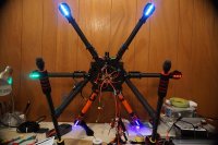
In my previous thread I was convinced that 680 is not enough for aerial photo, so 810 was selected.
Selected and ordered parts:
T810 frame
T-motors MN4010-14 370kv
T-motors ESCs S35A
T-motors props 15x5
DJI Naza M V2
Futaba T8J + R2008SB
2x Turnigy 6s 6000mAh 25-50c

Parts are starting to arrive, so I'm trying to attach them together.
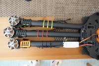
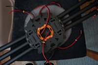
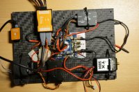
Assembled frame, realized that it is pain to get wires through arms on the assembled frame. Took it apart, put wires through, assembled. Realized that I don't have enough space on the plates for all components. Didn't want to move batteries under, neither use extra plates for multi-decker design.
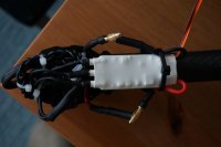
Pulled wires back from arms outside and fixed them with color-coded plastic ties. Going to place ESCs on the arms as shown. It would provide more space while keeping ESC-battery wires not very long. Hope this type of assembly is not the most crucial issue in balance and mass center position.
View attachment 23906
 

Attachments

  • DSC00478.JPG
    DSC00478.JPG
    138 KB · Views: 767

eskil23

Wikipedia Photographer
I thought the motor mounts had room for the ESCs.

One thing that I find appealing with the multi-deck design of the T810 is the possibillity to mount arms on different levels and therby providing vertical separation for overlaping propeller arcs.


Hm.. I don't quite understand how to deal with receiver power supply. I have Futaba R2008SB with 8 channels. According to manual, power supply by servo cable goes into channel 8. But in this case, I have only 7 channels left and it is not an 8 chanels receiver anymore. Am I missing something?
 

Apparently, both 8th channel and power supply go to the same slot, found this Y-harness in the box
View attachment 23957

After reading of different topics at different forums I got an impression that length of ECS to battery wires seem to be a kind of religious question, similar to wires discussion in Hi-End audio. At least, I haven't found any direct experiment: two same motors, two same ESCs, two different lengths of wire, X hours/days of constant work-> comparison and conclusions.
Therefore, I just moved ESCs to the designated places under the motors. Put wiring inside of arms. 4mm2 (11 AWG) wires with 4 mm bullet connectors I used look a bit like an overkill compared with 16 AWG wires from ESC, but let it be. Now just waiting for PDB with voltage step down outputs to connect all components and start tuning.View attachment 23958 View attachment 23959
 

Attachments

  • DSC00485.JPG
    DSC00485.JPG
    92.9 KB · Views: 500
  • DSC00483.JPG
    DSC00483.JPG
    48.8 KB · Views: 503
  • DSC00484.JPG
    DSC00484.JPG
    99.5 KB · Views: 470

Old Man

Active Member
You are correct in your assumption that a power input lead and channel output can share the same port. The power buss in a receiver is common to all the output ports so power is power regardless of where it inputs with the exception of Sbus receivers. For those you cannot input power at the Sbus ports.

I share your view of the contentiousness of short versus long ESC wires. I've heard pros and cons of each method but have yet to see substantive proof to validate either method. However, it does make sense to use the shortest combination of wire lengths possible to get the job done.

You'll find you'll run out of real estate quickly with that big hole in the middle of the top plate. Mounting essentials can become an issue. Obtaining a spare under frame battery mount may prove helpful. Try to keep the power distribution board as close to the bottom plate as possible. There are far too many ways to mount a gimbal on the market and few gimbals use a standardized mount. This leaves the user with the issue of adapting a mount to fit the frame or adapting the frame to fit the mount. Adapting the frame is easier if you obtain an extra set of center plates and some stand offs. That will allow mounting another bottom plate under the existing one for mounting a gimbal or gimbal hardware. One only needs stand offs long enough to clear the power distribution board. This also provides a little extra deck space under the aircraft for mounting small things like BEC's. The 810 will carry a decent size gimbal and camera.

I needed some place to mount lights so my ESC's are mounted on the arms just outside of the center plates.
 

Attachments

  • DSC00338-B.jpg
    DSC00338-B.jpg
    192.1 KB · Views: 374

Old Man

Active Member
Now that's bad. Shooting the picture just told me I need to reverse the green and red lights. Obviously wasn't paying attention to front and back when I put them on.... Supposed to be green-right, red-left, white-aft and blue-forward. Details, details:rolleyes:
 

It seems that I'm starting to run into troubles right from the start.

1. Performed ESCs calibration today. 5 motors were ok, but one didn't start in the beginning, just performed a bit of jerky movements for a few seconds, then spark occurred inside of the motor and it started to rotate. But it went considerably warm during 10 seconds rotation. Should I contact seller and ask replace the motor?

2. After the first disaster, I continued playing with other 5 motors, because I was concerned about a bit uneven sound from one of them. But at some moment receiver just lost connection. Led was red all the time. Voltage was fine and restarting of transmitter didn't help. Tried to press button on receiver to pair it again, but no effect. What could it be?
 

eskil23

Wikipedia Photographer
1) Yes, sbsolutly.
2) Good for you it happend on the ground and not in the air. ;-)
 

Hm, regarding the motor fail. Stupid, but I've realized that carbon frame is somewhat conductive, at least between some spots. Could failure be caused by some voltage on the motor mount base?
 

I had a similar problem with t-motor 4014's on my 810, the motor mount screw's provided by t-motor were to long and caused a short when tightened all the way in. I changed them all out for shorter ones.

I mounted the esc's and power distribution under the bottom plate, then bought additional bottom plates to cover and mount gimbals, one has my h3 3d gimbal and go pro the other I'm setting up with a bigger camera and gimbal, then you can just swap out the plates with the gimbal and its electronics attached.

I use a 12mm rail mount on these plates so I can mount the camera far enough forward to avoid seeing the props, then I mount the batteries behind and adjust them back and fourth until the copter is perfectly balanced.
 

Old Man and Joe Copter Pilot, thanks for comments
Yes, it seems that I need an extra layer to mount gimbal and retractable (I got motor-powered one) landing gear.
It is a bit strange, that only 2 plates set is available for T810, and it costs 70+ dollars. Actually I was thinking to buy 2 mm carbon fiber square plate, drill holes where necessary and attach it under. What is your opinion?

Regarding shortening of motor by screw.. Well, true, they are to long, but considering mounting plate, they should be just a bit below coil. Nevertheless, good idea, I'll replace them to shorter ones.


AzViper

Active Member
Using the Futaba Futaba T8J TX are you going to have enough channels for retracts, flight controls, and gimbal controls?
 

AzViper

Active Member
Old Man and Joe Copter Pilot, thanks for comments
Yes, it seems that I need an extra layer to mount gimbal and retractable (I got motor-powered one) landing gear.
It is a bit strange, that only 2 plates set is available for T810, and it costs 70+ dollars. Actually I was thinking to buy 2 mm carbon fiber square plate, drill holes where necessary and attach it under. What is your opinion?

Regarding shortening of motor by screw.. Well, true, they are to long, but considering mounting plate, they should be just a bit below coil. Nevertheless, good idea, I'll replace them to shorter ones.

That is why I went to multiple levels so that there is plenty enough room to mount the ESC's inboard and all the electronic's.

UTflTs.jpg
 

AzViper
I've changed the whole idea. I decided to go towards fully operational video system also. Therefore, I'm planning to use secons Tx for gimbal/camera. I guess, 4 ch should be enough. Trigger, pitch, yaw, roll (despite i'm not sure if anybody would need adjust roll manually)

P.S. What (and why) do you have mounted on one of your copter's arm, which is pointed towards us on the picture?
 

Joe Copter Pilot
I've ordered an A5 (15x21 cm) piece of 2 mm carbon fiber and a handful of long M3 x 50mm bolts. Going to mount it under, using 12 bolts holding unfoldable arms.

Set of 2 centerplates (like AzViper uses) would be great, but it is a pain to order anything to Europe from overseas. 80 USD on hobbyking mean extra 40-50 for tax and delivery
 

Failed Tx and motors were sent back to seller. While waiting for replacement, I was playing around with charger.
In the beginning I bought iMax B6 50W. Well, that's was a wrong choice. It went crazy after the only one charging of 6 Ah 6s battery, so I sent it back and acquired nice, colorful (and damn expensive) SkyRc 16 with power supply. This one seem to work nicely.
09.jpg
 

AzViper

Active Member
AzViper
I've changed the whole idea. I decided to go towards fully operational video system also. Therefore, I'm planning to use secons Tx for gimbal/camera. I guess, 4 ch should be enough. Trigger, pitch, yaw, roll (despite i'm not sure if anybody would need adjust roll manually)

P.S. What (and why) do you have mounted on one of your copter's arm, which is pointed towards us on the picture?

That is the Naza LED. It was mounted on the arm cause I had some extra clamps and this allowed to turn it so I could see the LED while on the ground and in the air.
 

Well, finally got all parts replaced or re-odered. Mounted all electronics on the additional carbon fiber plate.
Upon powering the system, led flashes as it should, but also strange hissing sound coming apparently from Naza module appears. Is it normal?
View attachment 24591
 

Attachments

  • DSC00607.JPG
    DSC00607.JPG
    147.3 KB · Views: 480

Top