COMike93yj
Still Building!
Hello Everyone!
Many of you are starting out and might want to purchase a charger for your batteries that might be a bit cheaper than some of the commercial alternatives that are out there. Many of the chargers out on the market require a separate power supply that might be really EXPENSIVE! For under $20 bucks you can make one that will serve you well and save the funds for things that can get you in the air!
------------------
Well I have been following a TON of threads out there that have led me to make a DIY Power supply out of readily available server power supplies.
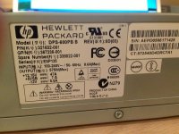
I am using a HP Model DPS-600 PB unit that puts out 575W.....it is a great little unit at 3.5 lbs.....
There are TONS of threads out there that enable you to make one (they are literally 10 bucks or so on Ebay) but I wanted to show you how easy it is to make one.
I WILL NOT be responsible for ANY harm or damage to property, people, pets...etc......
------------------------------------------
You can purchase these server power supplies from Ebay or Craigslist. These are designed to run 24/7 to provide power to servers in computer warehouses and they can withstand constant power and heat.
I am NOT detailing how you can use a DPS-600PB in Serial mode where you can achieve 24V and get upwards of over 1000W but there are tons of threads on RCGroups and other sites that will detail this. Once I
find a need to do so I will post up a tutorial on that")
So without further ado.......here is my pic intensive method on how I made one of these server power supplies to power a charger.
----------------
I am using a Hewlett Packard Model DPS-600PB server power supply. The reason I went with this is because I saw several threads on the internet that clearly illustrate how to convert one of these heavy duty
power supplies into an RC charger power supply.
-----------------
STEP ONE:
Get yourself a server power supply (in this case an HP DPS-600PB)!
View attachment 19482
REMEMBER....these have capacitors inside and I do NOT advocate cutting into them to do anything other than making a 12V power supply for your use. There are MANY threads that explain how to turn these on (what I am doing) and supplying power to your charger. You CAN make a 500W+ power supply to power your charger!!!!!!!
-----------------
STEP TWO:
You will need a computer power cord to make this work. If you have them laying around you can use them. If not, you can go to Monoprice.com to obtain one ( I actually purchased a Y power cord as eventually I will put two of these in series to make a 24v power supply for a charger).....
There are many threads that explain how to configure the ribbon cable inside the DPS-600PB but I elected to do the simple route and just jump the pins. Just my EASY way with things on hand to cause it to power on. THIESE are outstanding threads to help you do the things you might want to do........
http://www.rcgroups.com/forums/showthread.php?t=1581061
http://www.ultimaterc.com/forums/showthread.php?t=174225
Just follow the information in there and you will be well on your way!
------------------
STEP THREE:
Because these power supplies are designed to work in server racks and computer banks that require constant power, these are not designed for RC use. We have to be able to "convert" them to our use....aka providing power to our chargers!
This can be accomplished by "tricking" the DPS-600PB to power on.....this may sound simple but just plugging a computer cord into the power supply will NOT give us the power we need for our chargers!
WE NEED to do something to make it work!
This can easily be accomplished by creating a set of jumpers to make the Power supply give us the power we need!
There is a TON of information on this and you should all look at the threads mentioned earlier.
Essentially we have to "short" the pins on the front of the unit (in my case....you can do the ribbon mod but I am NOT doing this) to make the PSU "think" that it is on. I have also jumped the "fan" so that it is quieter but still will ramp up when needed under load.
Sorry I omitted this earlier but this is a site you should ALL go to..... -------> https://sites.google.com/site/tjinguytech/my-projects/HP47A
SOOOOO.... you picked up these power supplys on the cheap and when you plug them in they are NOT supplying your voltages........We have to turn them on!!!!! I will tell you how to do that!!!!
In order to turn the PSU's on...you have to "coerce" the PSU to think that it is powering something. It really isn't that hard to "coerce" the PSU to work for our needs. We simply have to make some adjustments to the PSU to "THINK" that it is applying power.....this is what this thread is going to achieve!
BEFORE PROGRESSING: I can not and will not be responsible for ANYTHING that happens if you decide to attempt a PSU conversion such as contained in this thread. This is for informational purposes only.
Multirotorforums.com and I will NOT and CAN NOT be held responsible for ANY issue that arise from this INFORMATIONAL post.
.....................................?
Still with me?????
OK lets progress.......
We need to "coerce" or "convince" the DPS-600PB to think it is applying power to some device (AKA your CHARGER....this is what we are after!)
NOTE: If you happened to order one off the internet and you simply plug it in you MAY ( you should ) get a fan that comes on but you may not get the appropriate power out of the leads on the front. If this confuses you just get a multimeter and test the outputs just below the fan.
In my experience, you have to get the green LED light by the power plug to glow green. This, IMO, indicates that the HP PSU is providing power to the leads near the fan.
To do this we have to "short" the pins located below the fan to "trick" the PSU into providing power. PLEASE LOOK AT THE THREADS I LINKED TO EARLIER!!!!
------------------------------------------------------------------
STEP FOUR:
Assuming you have obtained a HP DPS-600PB power supply from a server we will need to short out some "pins" on the front of the unit just below the fan unit. There are many threads about working with the ribbon cable that is internal to the power supply but I am showing how to make it workk without opening up the case and messing with the ribbon cable. The threads that I posted earlier in the links can show you all how to do this but THIS thread/post is not about that.
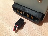
View attachment 19484
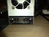
The above picture illustrates the FRONT side of the PSU. If you look in the center of the picture there is a "PIN" layout that has four rows of THREE pins.
This is convenient for us RC folks. WHY? The pin layout is a PERFECT match for servo cables!!!!!!
The pins, in the case of the DPS-600PB, go across from the top left (left to right) as one, two three...next level down goes four, five, six...next level is seven, eight, nine....then finally ten, eleven,
twelve.
View attachment 19485
I wish I could take credit for the picture but I can't find the person that originally posted it. (need citation)
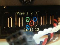
NOTICE: We only need to short out the pins circled in the picture above!!!
----------------------------------
STEP FIVE:
PREP WORK!
I am using servo cables that have the PERFECT fit for the pins on the PSU (HP DPS-600BPB server power supply unit)
The servo ends work PERFECTLY......trust me they work. You can determine if you want to solder ends onto the pins but I do not trust my soldering skills so I elected to go with the "BUILD" that I am doing)
View attachment 19487
You will NEED three of the connectors as illustrated above to do MY modification.......
Just so you know.....we are still shorting out the pins. We have to do this so that the PSU can power up and make our chargers work.
Here is the layout so you understand what you are doing!
Here is the diagram that I am trying to describe....Look from the TOP LEFT and read across (ONE PIN, TWO PIN, THREE PIN, then GO DOWN.....there are FOUR rows of pins.......
0 0 0
0 0 0
0 0 0
0 0 0
If you start at the top left that is PIN 1....go right and you will see that there are pins two and three.
Next row...you will see four, five, six......
Next row...you will see seven, eight, nine.....
Bottom row....you will see ten, eleven, twelve...
Pretty simple right??????
So if we are connecting the jumpers it would look like this on a DPS-600PB.....(X represents the pins we want to short out or "JUMP" )
0 0 0
X 0 X
0 X 0
X 0 0
This corresponds to this picture.....
View attachment 19485
LOOK CLOSELY at the above picture (citation still needed)........
ONE, TWO, THREE...... then go down a row....
FOUR, FIVE, SIX......then go down a row....
SEVEN, EIGHT, NINE......then go down to the final row......
TEN, ELEVEN, TWELVE.
Recall that we need to have the FOUR, SIX, EIGHT, and TEN pins "shorted"......I will show you later how to make this happen
REMEMBER: we are JUST trying to turn this PSU ON that was designed for computer server racks to keep data......we HAVE to turn it on to power our RC chargers!!!!!!
---------------------------------------
STEP SIX:
Once you know the way to turn the server power supply ON.....we can progress to how YOU can make it work for your charger!
MY METHOD......it is not as "sleek" as Feather mechant or other folks but it WORKS and is very simple........as simple as following instructions! Will my "modification" work to get the most power out of a
charger and charge batteries in seconds......NOT AT ALL.....it is simply a 575w power supply (with 10% degradation for connectors, cabling, etc) at 12 volts (actually from testing it is more like 12.5-7v)....
OK with my "aside"....we are ready to make it work for YOU!!!!!!!!!!!!!!!!
Now that we know what pins need to be "jumped/shorted" we need to fabricate a way to do so. This can be complicated...especially if you have soldering skills like I do (My skills SUCK).....
I purchased some SERVO CABLES that are OUTSTANDING for this simple mod! They are NOT designed for this purpose but TRUST ME they work and they will work for ANYONE following along!!!!
Grab yourself some simple SERVO CABLES....they simply work and they fit the DPS-600PB perfectly!
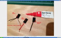
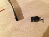
Cut or trim them like this.....
View attachment 15592
Pictures always help!
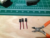
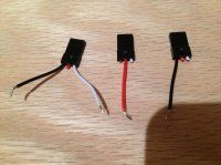
Take THREE simple servo connectors and DO THIS!!!
View attachment 15590
The reason I am triming the servo cables in this manner is because the wires need to "connect" to each other....aka short to ground. If you look in the above picture you will see how I trimmed the servo cables to create our "PLUG"....the plug is what we will put into the PSU to make it function for our RC Charger!!!!
------------------------
STEP SEVEN:
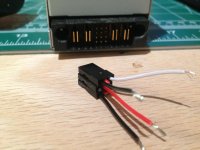
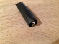
Now that we have made the servo connectors, trimmed the wires...we need to coil them together and "tin" them up. These wires are small so there is not a TON of heat to make a simple solder connection.
Here is what I did.....
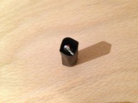
View attachment 15593
I stacked the servo connectors (one on top of the other)......I glued each of them together to make a 3x3 "plug" that fits nicely on the PSU...... Nice and neat for me!
NOTE: I cut back the wires to make them VERY close to the "plug"...this is not necessary but I wanted to make my "plug" close to the PSU.
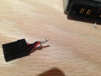
Once this was done I trimmed the wires.....this is a matter of preference....Trim them as you wish but make certain they are ALL connected to one another. I soldered them together and then trimmed them to length....
View attachment 15594View attachment 15595
You can see in the above photos that I soldered all of the wires together and then trimmed them to length.
------------------------------------------
STEP EIGHT:
At this point you can be finished!....
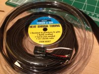
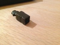
HOWEVER, I decided to put some heat shrink around the "plug" I made and it came out pretty well. I will refine this to cover the aft end but for this tutorial it will suffice!
Here are some pics.....
NOTE: The final version made better connections on the wires. The pics show some less than stellar connections that have been fixed.
Here you go!!!!!
View attachment 15596View attachment 15595View attachment 15597View attachment 15598View attachment 15599View attachment 15600
I used an Xacto knife to trim the heat shrink off so that the connector would fit perfectly! A dab of hot glue sealed the deal!!!!
--------------------
STEP NINE:
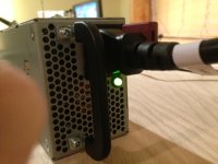
You HAVE to test your power supply......I will say this again........TEST YOUR POWER SUPPLY!!!!
Here are my results
MAKE CERTAIN YOUR PSU IS ON!!!!
View attachment 15601
Green light is GOOD!!!
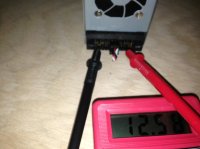
Now test for your output!!!
View attachment 15602
--------------------------------
STEP TEN:
Watch your output levels......be certain your charger can handle them......LOL....
Last few photos are not accurate as I pulled them from the phone earlier....I can say that the PSU mod is working spectacularly!
OK....TEN STEPS or LESS..........YOU can do this and save yourself a bundle of dough!!!! I am NOT an Electrical Engineer by any stretch of the imagination. PLEASE refer to the threads I posted earlier in the post. I am only showing you how I made these PSUs work.
In a few weeks I will do a tutorial on how to make these server supplies can work in series! The threads I posted earlier will show you how to do that but I feel that we should have a thread on making them work here at the Multirotorforums!!!
Cheers,
Mike
Many of you are starting out and might want to purchase a charger for your batteries that might be a bit cheaper than some of the commercial alternatives that are out there. Many of the chargers out on the market require a separate power supply that might be really EXPENSIVE! For under $20 bucks you can make one that will serve you well and save the funds for things that can get you in the air!
------------------
Well I have been following a TON of threads out there that have led me to make a DIY Power supply out of readily available server power supplies.
I am using a HP Model DPS-600 PB unit that puts out 575W.....it is a great little unit at 3.5 lbs.....
There are TONS of threads out there that enable you to make one (they are literally 10 bucks or so on Ebay) but I wanted to show you how easy it is to make one.
I WILL NOT be responsible for ANY harm or damage to property, people, pets...etc......
------------------------------------------
You can purchase these server power supplies from Ebay or Craigslist. These are designed to run 24/7 to provide power to servers in computer warehouses and they can withstand constant power and heat.
I am NOT detailing how you can use a DPS-600PB in Serial mode where you can achieve 24V and get upwards of over 1000W but there are tons of threads on RCGroups and other sites that will detail this. Once I
find a need to do so I will post up a tutorial on that
So without further ado.......here is my pic intensive method on how I made one of these server power supplies to power a charger.
----------------
I am using a Hewlett Packard Model DPS-600PB server power supply. The reason I went with this is because I saw several threads on the internet that clearly illustrate how to convert one of these heavy duty
power supplies into an RC charger power supply.
-----------------
STEP ONE:
Get yourself a server power supply (in this case an HP DPS-600PB)!
View attachment 19482
REMEMBER....these have capacitors inside and I do NOT advocate cutting into them to do anything other than making a 12V power supply for your use. There are MANY threads that explain how to turn these on (what I am doing) and supplying power to your charger. You CAN make a 500W+ power supply to power your charger!!!!!!!
-----------------
STEP TWO:
You will need a computer power cord to make this work. If you have them laying around you can use them. If not, you can go to Monoprice.com to obtain one ( I actually purchased a Y power cord as eventually I will put two of these in series to make a 24v power supply for a charger).....
There are many threads that explain how to configure the ribbon cable inside the DPS-600PB but I elected to do the simple route and just jump the pins. Just my EASY way with things on hand to cause it to power on. THIESE are outstanding threads to help you do the things you might want to do........
http://www.rcgroups.com/forums/showthread.php?t=1581061
http://www.ultimaterc.com/forums/showthread.php?t=174225
Just follow the information in there and you will be well on your way!
------------------
STEP THREE:
Because these power supplies are designed to work in server racks and computer banks that require constant power, these are not designed for RC use. We have to be able to "convert" them to our use....aka providing power to our chargers!
This can be accomplished by "tricking" the DPS-600PB to power on.....this may sound simple but just plugging a computer cord into the power supply will NOT give us the power we need for our chargers!
WE NEED to do something to make it work!
This can easily be accomplished by creating a set of jumpers to make the Power supply give us the power we need!
There is a TON of information on this and you should all look at the threads mentioned earlier.
Essentially we have to "short" the pins on the front of the unit (in my case....you can do the ribbon mod but I am NOT doing this) to make the PSU "think" that it is on. I have also jumped the "fan" so that it is quieter but still will ramp up when needed under load.
Sorry I omitted this earlier but this is a site you should ALL go to..... -------> https://sites.google.com/site/tjinguytech/my-projects/HP47A
SOOOOO.... you picked up these power supplys on the cheap and when you plug them in they are NOT supplying your voltages........We have to turn them on!!!!! I will tell you how to do that!!!!
In order to turn the PSU's on...you have to "coerce" the PSU to think that it is powering something. It really isn't that hard to "coerce" the PSU to work for our needs. We simply have to make some adjustments to the PSU to "THINK" that it is applying power.....this is what this thread is going to achieve!
BEFORE PROGRESSING: I can not and will not be responsible for ANYTHING that happens if you decide to attempt a PSU conversion such as contained in this thread. This is for informational purposes only.
Multirotorforums.com and I will NOT and CAN NOT be held responsible for ANY issue that arise from this INFORMATIONAL post.
.....................................?
Still with me?????
OK lets progress.......
We need to "coerce" or "convince" the DPS-600PB to think it is applying power to some device (AKA your CHARGER....this is what we are after!)
NOTE: If you happened to order one off the internet and you simply plug it in you MAY ( you should ) get a fan that comes on but you may not get the appropriate power out of the leads on the front. If this confuses you just get a multimeter and test the outputs just below the fan.
In my experience, you have to get the green LED light by the power plug to glow green. This, IMO, indicates that the HP PSU is providing power to the leads near the fan.
To do this we have to "short" the pins located below the fan to "trick" the PSU into providing power. PLEASE LOOK AT THE THREADS I LINKED TO EARLIER!!!!
------------------------------------------------------------------
STEP FOUR:
Assuming you have obtained a HP DPS-600PB power supply from a server we will need to short out some "pins" on the front of the unit just below the fan unit. There are many threads about working with the ribbon cable that is internal to the power supply but I am showing how to make it workk without opening up the case and messing with the ribbon cable. The threads that I posted earlier in the links can show you all how to do this but THIS thread/post is not about that.
View attachment 19484
The above picture illustrates the FRONT side of the PSU. If you look in the center of the picture there is a "PIN" layout that has four rows of THREE pins.
This is convenient for us RC folks. WHY? The pin layout is a PERFECT match for servo cables!!!!!!
The pins, in the case of the DPS-600PB, go across from the top left (left to right) as one, two three...next level down goes four, five, six...next level is seven, eight, nine....then finally ten, eleven,
twelve.
View attachment 19485
I wish I could take credit for the picture but I can't find the person that originally posted it. (need citation)
NOTICE: We only need to short out the pins circled in the picture above!!!
----------------------------------
STEP FIVE:
PREP WORK!
I am using servo cables that have the PERFECT fit for the pins on the PSU (HP DPS-600BPB server power supply unit)
The servo ends work PERFECTLY......trust me they work. You can determine if you want to solder ends onto the pins but I do not trust my soldering skills so I elected to go with the "BUILD" that I am doing)
View attachment 19487
You will NEED three of the connectors as illustrated above to do MY modification.......
Just so you know.....we are still shorting out the pins. We have to do this so that the PSU can power up and make our chargers work.
Here is the layout so you understand what you are doing!
Here is the diagram that I am trying to describe....Look from the TOP LEFT and read across (ONE PIN, TWO PIN, THREE PIN, then GO DOWN.....there are FOUR rows of pins.......
0 0 0
0 0 0
0 0 0
0 0 0
If you start at the top left that is PIN 1....go right and you will see that there are pins two and three.
Next row...you will see four, five, six......
Next row...you will see seven, eight, nine.....
Bottom row....you will see ten, eleven, twelve...
Pretty simple right??????
So if we are connecting the jumpers it would look like this on a DPS-600PB.....(X represents the pins we want to short out or "JUMP" )
0 0 0
X 0 X
0 X 0
X 0 0
This corresponds to this picture.....
View attachment 19485
LOOK CLOSELY at the above picture (citation still needed)........
ONE, TWO, THREE...... then go down a row....
FOUR, FIVE, SIX......then go down a row....
SEVEN, EIGHT, NINE......then go down to the final row......
TEN, ELEVEN, TWELVE.
Recall that we need to have the FOUR, SIX, EIGHT, and TEN pins "shorted"......I will show you later how to make this happen
The LEFT Servo connector will connect to the "4" pin and the "6" pin......(the four pin allows for the fan to run at low speeds until the temp raises.....then it will kick into "HIGH" mode under large loads)
The MIDDLE Servo connector will connect to the "8" pin........trust me this will make sense soon!
The RIGHT Servo connector will connect to the "10" pin.......keep following this will WORK.....
REMEMBER: we are JUST trying to turn this PSU ON that was designed for computer server racks to keep data......we HAVE to turn it on to power our RC chargers!!!!!!
---------------------------------------
STEP SIX:
Once you know the way to turn the server power supply ON.....we can progress to how YOU can make it work for your charger!
MY METHOD......it is not as "sleek" as Feather mechant or other folks but it WORKS and is very simple........as simple as following instructions! Will my "modification" work to get the most power out of a
charger and charge batteries in seconds......NOT AT ALL.....it is simply a 575w power supply (with 10% degradation for connectors, cabling, etc) at 12 volts (actually from testing it is more like 12.5-7v)....
OK with my "aside"....we are ready to make it work for YOU!!!!!!!!!!!!!!!!
Now that we know what pins need to be "jumped/shorted" we need to fabricate a way to do so. This can be complicated...especially if you have soldering skills like I do (My skills SUCK).....
I purchased some SERVO CABLES that are OUTSTANDING for this simple mod! They are NOT designed for this purpose but TRUST ME they work and they will work for ANYONE following along!!!!
Grab yourself some simple SERVO CABLES....they simply work and they fit the DPS-600PB perfectly!
Cut or trim them like this.....
View attachment 15592
Pictures always help!
Take THREE simple servo connectors and DO THIS!!!
View attachment 15590
The reason I am triming the servo cables in this manner is because the wires need to "connect" to each other....aka short to ground. If you look in the above picture you will see how I trimmed the servo cables to create our "PLUG"....the plug is what we will put into the PSU to make it function for our RC Charger!!!!
------------------------
STEP SEVEN:
Now that we have made the servo connectors, trimmed the wires...we need to coil them together and "tin" them up. These wires are small so there is not a TON of heat to make a simple solder connection.
Here is what I did.....
View attachment 15593
I stacked the servo connectors (one on top of the other)......I glued each of them together to make a 3x3 "plug" that fits nicely on the PSU...... Nice and neat for me!
NOTE: I cut back the wires to make them VERY close to the "plug"...this is not necessary but I wanted to make my "plug" close to the PSU.
Once this was done I trimmed the wires.....this is a matter of preference....Trim them as you wish but make certain they are ALL connected to one another. I soldered them together and then trimmed them to length....
View attachment 15594View attachment 15595
You can see in the above photos that I soldered all of the wires together and then trimmed them to length.
------------------------------------------
STEP EIGHT:
At this point you can be finished!....
HOWEVER, I decided to put some heat shrink around the "plug" I made and it came out pretty well. I will refine this to cover the aft end but for this tutorial it will suffice!
Here are some pics.....
NOTE: The final version made better connections on the wires. The pics show some less than stellar connections that have been fixed.
Here you go!!!!!
View attachment 15596View attachment 15595View attachment 15597View attachment 15598View attachment 15599View attachment 15600
I used an Xacto knife to trim the heat shrink off so that the connector would fit perfectly! A dab of hot glue sealed the deal!!!!
--------------------
STEP NINE:
You HAVE to test your power supply......I will say this again........TEST YOUR POWER SUPPLY!!!!
Here are my results
MAKE CERTAIN YOUR PSU IS ON!!!!
View attachment 15601
Green light is GOOD!!!
Now test for your output!!!
View attachment 15602
--------------------------------
STEP TEN:
Watch your output levels......be certain your charger can handle them......LOL....
Last few photos are not accurate as I pulled them from the phone earlier....I can say that the PSU mod is working spectacularly!
OK....TEN STEPS or LESS..........YOU can do this and save yourself a bundle of dough!!!! I am NOT an Electrical Engineer by any stretch of the imagination. PLEASE refer to the threads I posted earlier in the post. I am only showing you how I made these PSUs work.
In a few weeks I will do a tutorial on how to make these server supplies can work in series! The threads I posted earlier will show you how to do that but I feel that we should have a thread on making them work here at the Multirotorforums!!!
Cheers,
Mike
Attachments
-
 EDIT 1 PSU.jpg138.8 KB · Views: 1,356
 -
 photo(20).jpg140 KB · Views: 960
 -
 photo(19).jpg136.3 KB · Views: 1,041
 -
 photo(8).jpg135 KB · Views: 880
 -
 photo(9).jpg137.7 KB · Views: 1,260
 -
 photo(18).jpg141.7 KB · Views: 1,011
 -
 photo(10).jpg140.8 KB · Views: 941
 -
 photo(15).jpg151.9 KB · Views: 874
 -
 photo(16).jpg142.1 KB · Views: 975
 -
 photo(14).jpg142.8 KB · Views: 893
 -
 photo(32).JPG100.8 KB · Views: 942
 -
 photo(33).jpg105.6 KB · Views: 876