Aeronavics / Droidworx Pete's VM-6 Hexa build blog...

Efliernz

Pete
Pete's Droidworx VM-6 Hexa build blog...

I have built about 12 multirotors in the last two years... all diy - most scratch-built, some with X468 parts and my current octo from a "Rustys" hub.

While I do some video (not commercially), my main purpose is to fly a light-weight Sony RX100 for stills photography work. My octo does it now but I wanted something light, strong and new. About a month ago, Droidworx started updating their website and were featuring a new set of machines. The VM series replaces much of the AD series. While I would like a bigger machine, a basic VM-6 should suit my needs. Droidworx are also based only 40Km from me so postage wasn't an issue and I knew that support is literally "just around the corner".

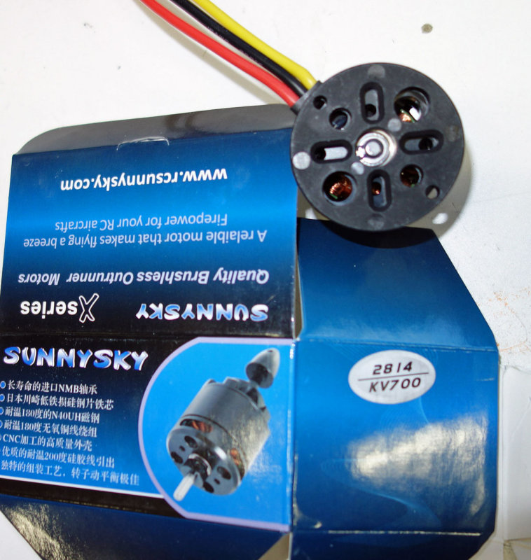
I am already flying a quad with Sunnysky 2814 700Kv 120 gram motors. They are not Axi's... but "good budget motors". They are at the top limit of what should be on this size hexa, so six were ordered.

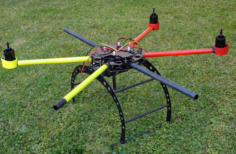
Why a hexa? My 770mm octo gets blown around in the wind more than my old heavy experimental hexa did - so a hexa it is. Orientation is also easier.
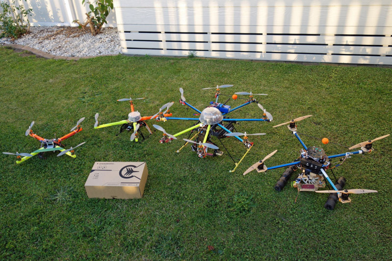
My current fleet:

146950847.jpg
 
Last edited by a moderator:

Efliernz

Pete
Unboxing...

Gee this box was small. I heard a Monty Python accent in the back of my mind "shoebox... luxury" as Linda and Lucy handed me the box!

146950846.jpg


First thing - download the PDF manual onto your pc or tablet (or paper) and have a read first. Despite being a male technician, I did read it!

Not much to show! The dome is in its own box. Carbon arms wrapped up as well as a few labeled bags of goodies. Mine also had a couple of chocolates in the box (ta heaps)...

146950849.jpg


Spread out on the table, everything is well labeled.

146950850.jpg
 

Efliernz

Pete
I was aware that my motors were at the large-end of what was recommended. I checked the bolt hole fitting first - just to put my mind at ease.

146950853.jpg


The manual shows which holes are used for what.

146950854.jpg

This is where I was different! I wanted an X-hexa, not a + hexa. When I mentioned this to Linda, she looked at me and said that it wasn't setup for X. Let me explain...

The u/c mounts are under the front and rear arm brackets using extra-long bolts. This is great if you are going +. As I was going X, the u/c mounting was between the arms. No worries... we all had a look at several of the assembled machines and Rob grabbed some 22mm standouts and bolts that are used on the VM-4 X machine - and some extra bits if required. I looked at the u/c brackets and noted that there are several sets of holes that fit several different frame / arm widths. I decided to use the outer holes.

146950855.jpg


I would need to drill the hubs to suit. This actually took quite a while to ensure that they were in the right place. I then bolted the two hubs together (to stop them moving) and through-drilled. As the hubs are symmetrical, I then flipped one of the hubs, re-bolted and through-drilled again to complete the new u/c holes, top and bottom.

146950856.jpg


Yes I turned the small arm guides around to taper into the middle as stated in the manual!


Efliernz

Pete
I like colours to help with orientation. I use flouro film from r/c planes and iron-shrunk the film onto the arms. Almost a crime to hide the awesome-looking carbon tube.

146950857.jpg


Assembly on a small wood panel made flipping it over without loosing all the bolts easy.

90 minutes to this stage, most of which was aligning the the u/c holes.

My first impressions are that everything fits perfectly. More building tomorrow.

Pete
 
Last edited by a moderator:


Thanks for sharing your experience, Pete. I dig your colorful fleet. Did you use some sort of iron to heat up the film on the arms? I put film on the arms of our Cinestar using a heat gun with decent results, all while wondering if an iron would've worked a lot better. Let me know what you used - I'd appreciate it.

Thanks,
Ben Rowland
 

Efliernz

Pete
Hi Ben.

Attempt #1. I first rolled the film around but I had about 1 1/2 layers - which ended up being too much. I pulled it as tight as I could, then used the covering iron to join the flap to the film underneath. Then I thought - hey... I'll get the heatgun out... and it all turned to poo after that! It was uneven, bubbled... it may have been better if I had less overlap. That all got ripped off (while hot so it would release the glue and I started again.

Attempt #2. A bit less film this time - 1 1/4 layers. I used the covering iron and stuck the edge to the tube all the way along. I then carefully and slowly slid the iron around the tube in appox 1/8 circumference movements while going up and down the tube. It took several minutes per tube. Results are very good :)

There must be an easier way but I guess 25 years rc planes has an advantage... Patience is required but the results are worth it. Btw, my VM-6 will still have lights too...

Pete


Efliernz

Pete
Yup they do... but I didn't have any (and it was 10pm and you know it's just got to be built!) and I like the vivid green :)
 
Last edited by a moderator:

Efliernz

Pete
This morning I leap into it and once again in my life, I find that I have chosen the difficult way to deal with something.

When one chooses to orientate their VM-6 as a X, the flight-controller adapter plate doesn't align with any of the pre-drilled holes in the hub. It was simply designed for a + layout. Not a big deal, I just need work out which adapter holes are going to be used by the HoverflyPro FC and where could I drill. Easy :)

First thing is to dissemble last nights work...

146959010.jpg


146959012.jpg

Clamp and align. Drill.

Pete's top tip! After I attached the FC adapter plate stand-outs, I drilled holes in a spare panel of wood in the same positions for the stand-out to sink into. This means that once all the bolts are placed back into the top plate and the plate flipped over, the bolt heads sit flat against the board with the stand-outs countersunk.

146959014.jpg


Hub done, FC adapter in place and the stand-outs for the HFP board are in position.

146959015.jpg
 

Efliernz

Pete
Time for something easy... the u/c. I am still working on my camera-mount so I'll throw this together, even though there will be changes.

Parts list... just like in the manual :)

146960165.jpg


In just a few minutes, it looks like this:

146960166.jpg


Pete's top tip: If the tubes are hard to push through the grommets, add a little dishwashing liquid around the tube (not on the end where the thread is).

Add dome mountings, the dome and stick it together and it almost looks like it should! The look is undeniably Droidworx ;)
665 grams so far.

146960167.jpg


Motor mounting time. I suspect that this will take a while. I need to plan the esc positions. I am using 40A Plushes so I have a heap of cooling headroom - so they can probably go anywhere.
 

nicwilke

Active Member
I am salivating... I can't wait for my kit. It's in Sydney, 6 hour drive from here. Will most likely arrive Monday. You'll be flying by then. I'll blog my build also.
 

Hi Ben.

Attempt #1. I first rolled the film around but I had about 1 1/2 layers - which ended up being too much. I pulled it as tight as I could, then used the covering iron to join the flap to the film underneath. Then I thought - hey... I'll get the heatgun out... and it all turned to poo after that! It was uneven, bubbled... it may have been better if I had less overlap. That all got ripped off (while hot so it would release the glue and I started again.

Attempt #2. A bit less film this time - 1 1/4 layers. I used the covering iron and stuck the edge to the tube all the way along. I then carefully and slowly slid the iron around the tube in appox 1/8 circumference movements while going up and down the tube. It took several minutes per tube. Results are very good :)

There must be an easier way but I guess 25 years rc planes has an advantage... Patience is required but the results are worth it. Btw, my VM-6 will still have lights too...

Pete

Thanks for the info. Much appreciated. I'll be trying technique #2 on my next build.

all the best,
Ben
 

Efliernz

Pete
I am salivating... I can't wait for my kit. It's in Sydney, 6 hour drive from here. Will most likely arrive Monday. You'll be flying by then. I'll blog my build also.

Mine wont be flying... I have motor size issues... For once in my life, what I have is too big! They are contacting the bolt heads. I'm looking at making spacers in a few minutes with smaller-bolt heads. Then the wiring and where the esc's are going to go. I'm only 20% there really!

If I had bought smaller motors, built it for + mode, I would be nearly finished...

Pete


Efliernz

Pete
I'm sorting the motors out and I have needed to get creative... and now they fit.

The red boots are standard DW 40mm boots, the green is a black one covered in iron-on film. It looks great (from 2 yards away...) but it will look awesome at 150' :D

146964000.jpg
 
Last edited by a moderator:

nicwilke

Active Member
I'm sorting the motors out and I have needed to get creative... and now they fit.

The red boots are standard DW 40mm boots, the green is a black one covered in iron-on film. It looks great (from 2 yards away...) but it will look awesome at 150' :D

146964000.jpg

Cool looking rig bud.

You mentioned soldering, and reminded me I have to go but a better soldering iron. I got me one of those fancy droidworx PDB's.
I think I'll be flying by Friday as I've got a big weekend.
 
Last edited by a moderator:

Efliernz

Pete
I still haven't decided how / where to put the esc's. I'm looking at AD builds online to get some tips. I think I will make longer standouts from the hub up to the FC adapter board and put them under the adapter board. The u/c isn't tall so I am needing to plan my camera gimbal carefully.

I'm done in the shed tonight. Crappy headache that drugs wont move. I had a really busy week with long hours last week and it has caught up with me I suspect.
 

Top