Aerial Media Pros
Member
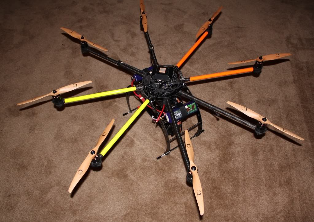
Hi guys, I Just finished building another AD8 Heavy Lift. I have a client wanting a heavy lift Octo using the Hercules boards. So I figured I should build one for myself, and thoroughly test it before recommending it to others. Since this was my first build using the much anticipated HERCULES Boards. I thought I would take some pics along the way, and do a quick build thread. Just a warning, I am by no means a master at this, and I am constantly open to learn new things. This is my first build thread so take it easy on me. I would like to note that allot of this build was accomplished, only with the help of fellow forum members. Without their support, I would have never gotten into this hobby. Anyway, hopefully this build will give some ideas or help someone else that has a similar build in mind. I have included a few tips that I feel work great. Feel free to ask me any questions, and I’ll do my best to answer them.
So here it is,the recently completed AD8 HERCULES BUILD
First I put together the parts list and began getting everything together for the build.
PARTS LIST
AD8 Heavy Lift Extended (I ordered 2 extra booms, extra motor mount, Extra landing gear set)
Dual Battery Tray
(8) QuadroPower QC3328 Motors
AV200 Pro Mount, AV200 PRO w/ 360
(2) Flight Control V2.1 ME (1 for AD8, 1 for AV200 360)
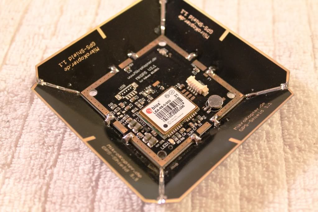
MK GPS V2.1 and MK GPS Shield 1.1
Navi-Ctrl V2.0
(2) Hercules Power Board Pro
Active Cooling plate for Hercules October
Hercules USB
MK USB
XBEE Wireless Communication Set
PCB Extension (to Operate LED’s)
6V BEC for AV200 Servos
DC/DC 12v regulator for PCB
(5) Pairs Xoar 13x6.5 Beachwood props for testing (all props I have drilled to 6mm, to fit perfect to the MK or AXI prop adapters)
(5) Pairs Carbon Fiber 13x6.5 props for Filming
(8) 6mm prop adapters
(8) Turnigy Nano Tech 4S 6000mAh Lipo's
(4) Sky Lipo's 3S 2200mAh (For the AV200 360 servos and downlink)
JR 11x Transmitter
Spektrum AR9100 Receiver (for the 3 Satellites)
Spektrum Diversity Board
High Intensity LED’s (red and green)
Servo Wire (came in 50 foot length)
Deans Connectors
Servo plugs (DIY for making LED, PCB, Buzzer Connections and such)
Servo Wire Wrap
1 ½” Clear heat Shrink Tubing (to cover LED’s)
This was pretty much everything excluding a few odds and ends that I already had.
This copter should easily get 10 minutes flight time while carrying a Canon 7D with downlink gear. I will be flying (2) 4S 6000mAh packs in Parallel.
AD8 HLE FRAME ASSEMBLY
I first open all the misc frame parts and components. I lay everything out nice and neat putting all similar parts and screws together in their own little piles. This also gives me the opportunity to inventory everything making sure I am not missing anything.
Once you have a nice area arranged and to work on. Follow the following Build manuals from Droidworx.com.au.
Here is the Main Download page for Assembly instructions.
http://www.droidworx.com.au/assembly2.html
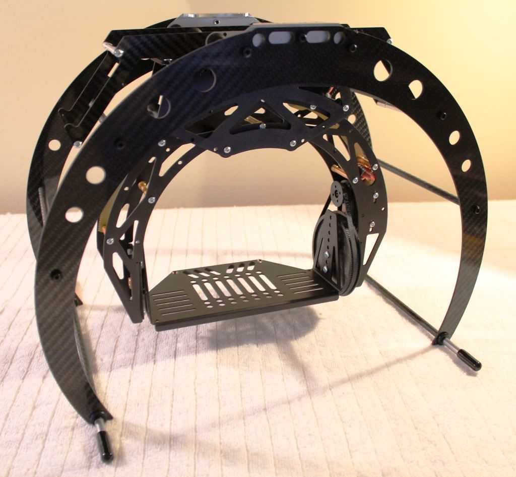
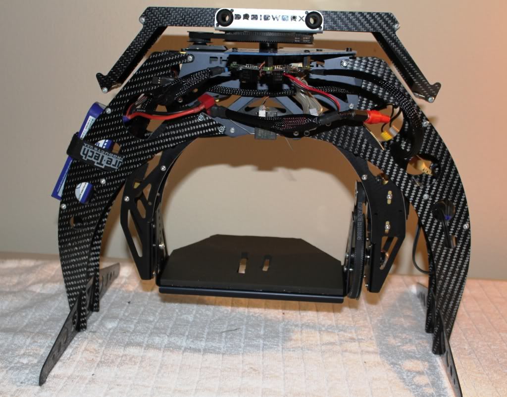
LANDING GEAR ASSEMBLY
This part of the process was pretty simple. Just make sure all the screws into the AV200 are tight. (I even opted to use a small amount thread lock on the metal to metal parts). I also use a tab of CA glue on the screws that went into the Carbon tubes.
I ordered and installed the Dual battery tray. You can mount them directly under the center plates. But this accessory makes the Lipo’s mounting/removal very easy. Be sure to thread lock the screw on this part.
HUGE RECOMMENDATION!!
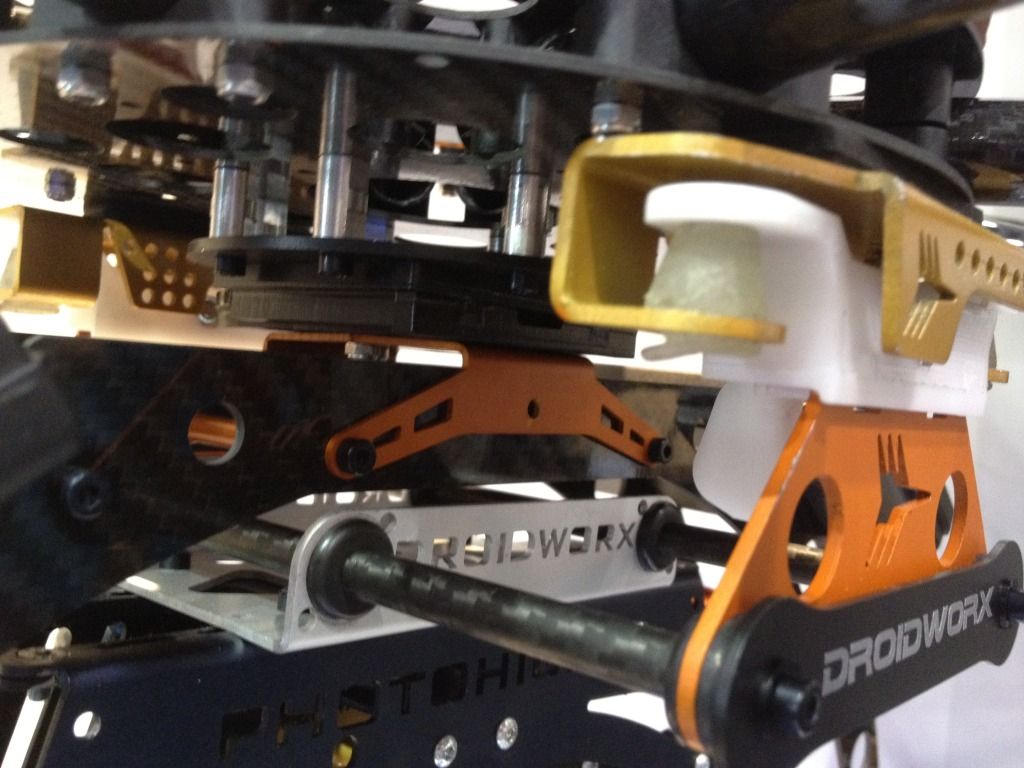
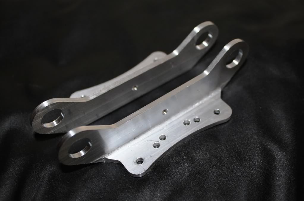
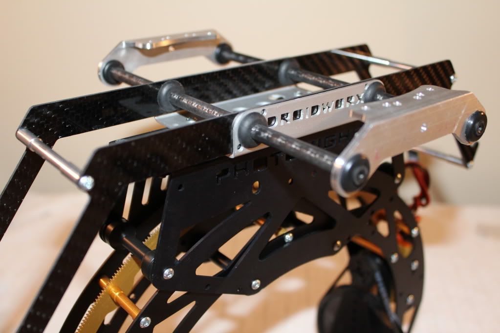
The stock Gear rail brackets that come with the frames are pretty weak. I had noticed stress fractures in my stock ones. Because I haveThousands of $ in camera gear and gimbals hanging from these two brackets. I decided to CNC Machine my own ALUMINUM GEAR RAIL BRACKETS. The parts I made are extremely durable, and yet they are very light. I feel this is a must have upgrade for anyone carrying nice cameras with pricey Gimbals.
The Stock Plastic Gear rail brackets cost $45 plus shipping. I sell mine for $44 Shipped. Contact me if you would like a set. I am running another batch this week, and they will be anodized Black.
I use both the AV200 with Extended landing gear, and a separate AV200 on 360. When I am flying alone, I use the 2 axis. When I have my camera man operating the gimbal, I quickly switch to the 360.
Here are a couple pics showing the process and then the two completely assembled.
FRAME ASSEMBLY
Some things to pay close attention to here are. To make sure the Boom Brackets are facing in the correct direction. Make sure the Motor mount locating hole (on the outside end of the boom) is on the top. When looking at the top of your frame, you should see this hole. On my first AD8 Build, I had one that was upside down, and it can be a pain flipping it over. Check your standoff mounting locations with your electronics; just to be sure they are int he correct place.
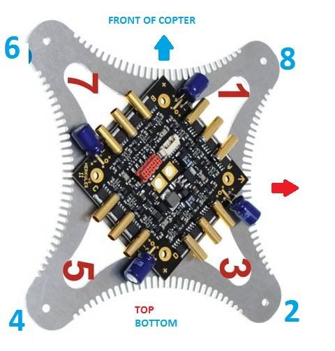
When Using the HERCULES Cooling Plate. There ARE NOT holes in the center frame plates to mount the standoffs, that would line up with the Active cooling plate. You will need to line up and drill 4 small holes. That way you can mount the stand offs lining up correctly to the Hercules cooling plate. Make sure the way you mount it has the arrow on the FC board Pointing right BETWEEN Motors 1 and 2. It should point towards the Notch in the Centerplate.
Here is a Pic with RED drawing showing the Direction, andwhere I had to drill the 4 mounting holes.

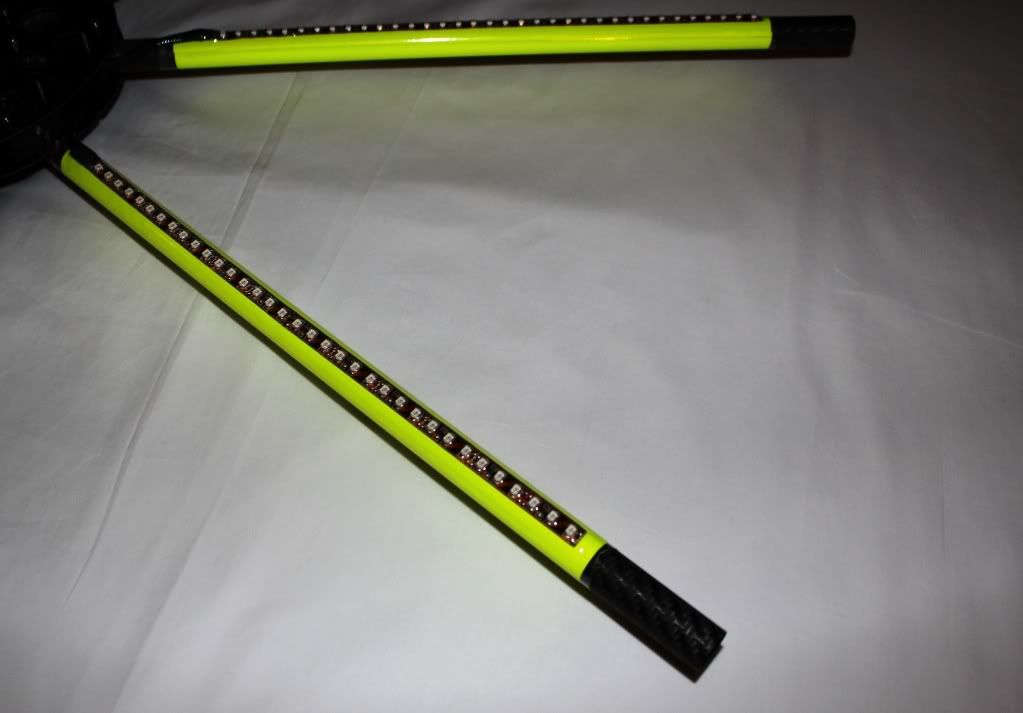
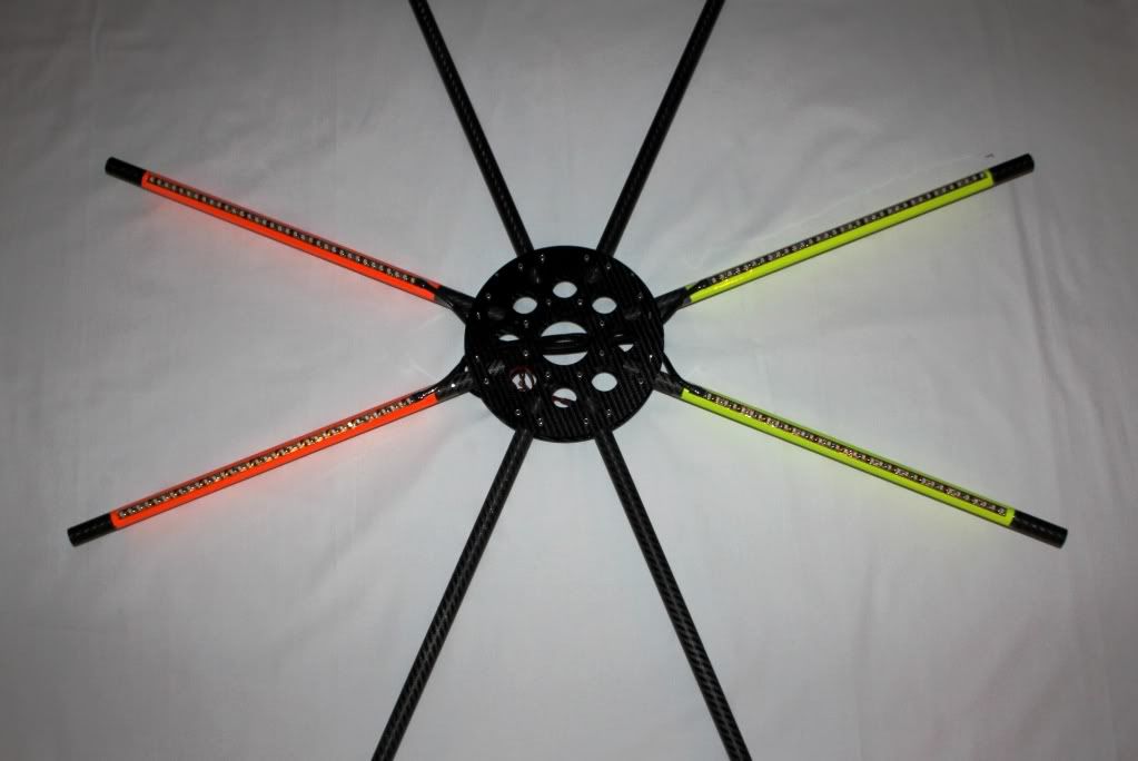
TIPS during Frame assembly: If you are using LED’s.
I prefer to mount any orientation tape to the booms. I then lay the LED’s in their place. And finally I use 1 ½” Clear Heat Shrink to cover them. Get a decent heat gun to make this process easy. This makes for a really clean and professional looking install. Mainly it gets rid of having to use zip ties. Do this before putting the motor mounts on, or you won’t be able to get the Heat shrink on (trust me on this hehehe). I also use this time to run any wires that you may want down the booms. Some like to run a wire to the end of a boom for the buzzer.
After installing the LED’s and Heat Shrink, they should looksomething like this.
Here is my completed frame. Ready to have the motors mounted.
MOTOR MOUNTING AND INSTALL
I like to prep the motor wires before mounting them. If youare using MK 3638’s like I did in a previous build. Then you may want to tin the wires before mounting the motors. I found this makes it easier and keeps the wires from getting frayed as you route them.
Place the 30mm screw through the motor mount disc before mounting it to the motor. When using the larger motors, you will not be able to get the screw in place once the motor is mounted to the disc. Again, I learned this the hard way.
I like to thread lock the screws going into the motor. On an older build, I used a screw that was 2mm longer. I felt that there was not enough threads going into the motor, and a little longer screw gave plenty more bite. Personally it just gave me a little more assurance.
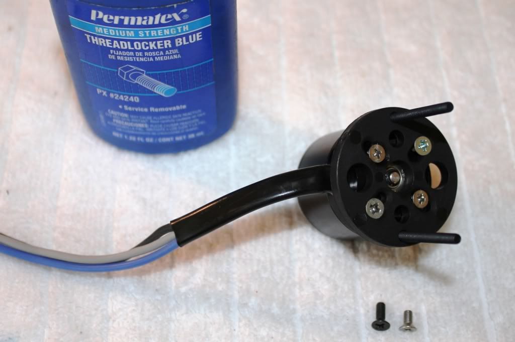
APPLY HEAT SHRINK TUBING TO MOTOR WIRES.
This is a big must in my book. I put heat shrink over the motor wires right at the can. This helps protect the wires from rubbing against the carbon edge of the boom and shorting out.
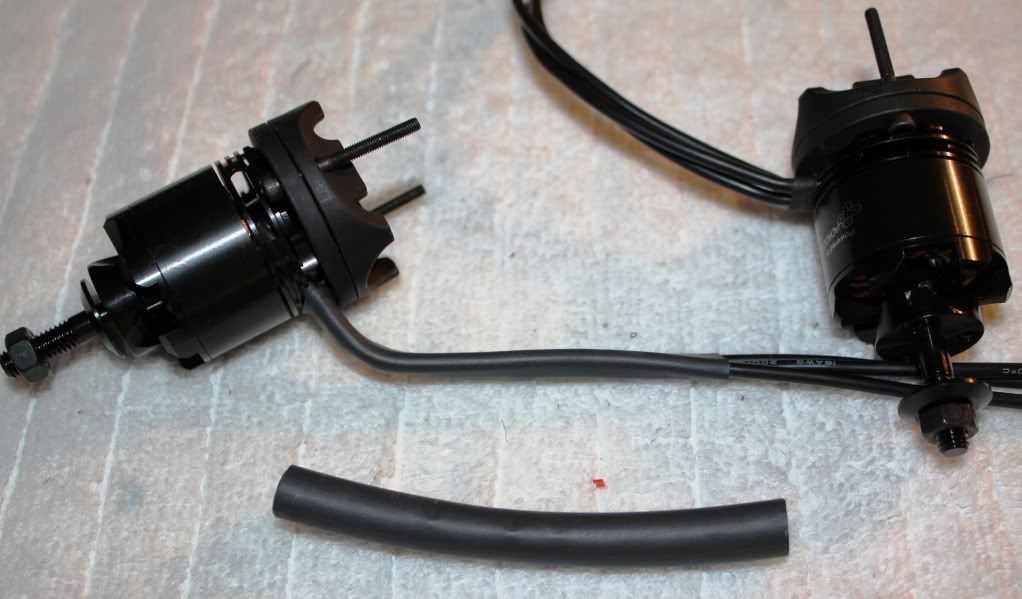
Before installing the 6mm prop adapters, I thread lock and tighten the Set screws that hold the can to the motor shaft. I also thread lock the 3 screws used to mount the prop adapters. I do this to make sure they do not come loose, causing off balance vibrations. It also helps to ensure the prop stays on the motor.
Finally Go ahead, feed the wires through, and mount these bad boys onto the booms, ensuring the dimple in the mount lines up with the hole in the top of the boom.
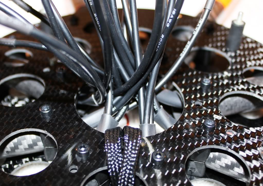
Once you get the motors all mounted, and the wires all fed through. Go ahead and apply Heat shrink where the wires exit the interior of the boom. This will help protect the wires from the edges of the booms, and center plate.
This should finish up the AD8 Frame and Landing gear. Now it’s time to move on to the Electronics.
CONTINUED IN FOLLOWING POSTS
So here it is,the recently completed AD8 HERCULES BUILD
First I put together the parts list and began getting everything together for the build.
PARTS LIST
AD8 Heavy Lift Extended (I ordered 2 extra booms, extra motor mount, Extra landing gear set)
Dual Battery Tray
(8) QuadroPower QC3328 Motors
AV200 Pro Mount, AV200 PRO w/ 360
(2) Flight Control V2.1 ME (1 for AD8, 1 for AV200 360)
MK GPS V2.1 and MK GPS Shield 1.1
Navi-Ctrl V2.0
(2) Hercules Power Board Pro
Active Cooling plate for Hercules October
Hercules USB
MK USB
XBEE Wireless Communication Set
PCB Extension (to Operate LED’s)
6V BEC for AV200 Servos
DC/DC 12v regulator for PCB
(5) Pairs Xoar 13x6.5 Beachwood props for testing (all props I have drilled to 6mm, to fit perfect to the MK or AXI prop adapters)
(5) Pairs Carbon Fiber 13x6.5 props for Filming
(8) 6mm prop adapters
(8) Turnigy Nano Tech 4S 6000mAh Lipo's
(4) Sky Lipo's 3S 2200mAh (For the AV200 360 servos and downlink)
JR 11x Transmitter
Spektrum AR9100 Receiver (for the 3 Satellites)
Spektrum Diversity Board
High Intensity LED’s (red and green)
Servo Wire (came in 50 foot length)
Deans Connectors
Servo plugs (DIY for making LED, PCB, Buzzer Connections and such)
Servo Wire Wrap
1 ½” Clear heat Shrink Tubing (to cover LED’s)
This was pretty much everything excluding a few odds and ends that I already had.
This copter should easily get 10 minutes flight time while carrying a Canon 7D with downlink gear. I will be flying (2) 4S 6000mAh packs in Parallel.
AD8 HLE FRAME ASSEMBLY
I first open all the misc frame parts and components. I lay everything out nice and neat putting all similar parts and screws together in their own little piles. This also gives me the opportunity to inventory everything making sure I am not missing anything.
Once you have a nice area arranged and to work on. Follow the following Build manuals from Droidworx.com.au.
Here is the Main Download page for Assembly instructions.
http://www.droidworx.com.au/assembly2.html
LANDING GEAR ASSEMBLY
This part of the process was pretty simple. Just make sure all the screws into the AV200 are tight. (I even opted to use a small amount thread lock on the metal to metal parts). I also use a tab of CA glue on the screws that went into the Carbon tubes.
I ordered and installed the Dual battery tray. You can mount them directly under the center plates. But this accessory makes the Lipo’s mounting/removal very easy. Be sure to thread lock the screw on this part.
HUGE RECOMMENDATION!!
The stock Gear rail brackets that come with the frames are pretty weak. I had noticed stress fractures in my stock ones. Because I haveThousands of $ in camera gear and gimbals hanging from these two brackets. I decided to CNC Machine my own ALUMINUM GEAR RAIL BRACKETS. The parts I made are extremely durable, and yet they are very light. I feel this is a must have upgrade for anyone carrying nice cameras with pricey Gimbals.
The Stock Plastic Gear rail brackets cost $45 plus shipping. I sell mine for $44 Shipped. Contact me if you would like a set. I am running another batch this week, and they will be anodized Black.
I use both the AV200 with Extended landing gear, and a separate AV200 on 360. When I am flying alone, I use the 2 axis. When I have my camera man operating the gimbal, I quickly switch to the 360.
Here are a couple pics showing the process and then the two completely assembled.
FRAME ASSEMBLY
Some things to pay close attention to here are. To make sure the Boom Brackets are facing in the correct direction. Make sure the Motor mount locating hole (on the outside end of the boom) is on the top. When looking at the top of your frame, you should see this hole. On my first AD8 Build, I had one that was upside down, and it can be a pain flipping it over. Check your standoff mounting locations with your electronics; just to be sure they are int he correct place.
When Using the HERCULES Cooling Plate. There ARE NOT holes in the center frame plates to mount the standoffs, that would line up with the Active cooling plate. You will need to line up and drill 4 small holes. That way you can mount the stand offs lining up correctly to the Hercules cooling plate. Make sure the way you mount it has the arrow on the FC board Pointing right BETWEEN Motors 1 and 2. It should point towards the Notch in the Centerplate.
Here is a Pic with RED drawing showing the Direction, andwhere I had to drill the 4 mounting holes.
TIPS during Frame assembly: If you are using LED’s.
I prefer to mount any orientation tape to the booms. I then lay the LED’s in their place. And finally I use 1 ½” Clear Heat Shrink to cover them. Get a decent heat gun to make this process easy. This makes for a really clean and professional looking install. Mainly it gets rid of having to use zip ties. Do this before putting the motor mounts on, or you won’t be able to get the Heat shrink on (trust me on this hehehe). I also use this time to run any wires that you may want down the booms. Some like to run a wire to the end of a boom for the buzzer.
After installing the LED’s and Heat Shrink, they should looksomething like this.
Here is my completed frame. Ready to have the motors mounted.
MOTOR MOUNTING AND INSTALL
I like to prep the motor wires before mounting them. If youare using MK 3638’s like I did in a previous build. Then you may want to tin the wires before mounting the motors. I found this makes it easier and keeps the wires from getting frayed as you route them.
Place the 30mm screw through the motor mount disc before mounting it to the motor. When using the larger motors, you will not be able to get the screw in place once the motor is mounted to the disc. Again, I learned this the hard way.
I like to thread lock the screws going into the motor. On an older build, I used a screw that was 2mm longer. I felt that there was not enough threads going into the motor, and a little longer screw gave plenty more bite. Personally it just gave me a little more assurance.
APPLY HEAT SHRINK TUBING TO MOTOR WIRES.
This is a big must in my book. I put heat shrink over the motor wires right at the can. This helps protect the wires from rubbing against the carbon edge of the boom and shorting out.
Before installing the 6mm prop adapters, I thread lock and tighten the Set screws that hold the can to the motor shaft. I also thread lock the 3 screws used to mount the prop adapters. I do this to make sure they do not come loose, causing off balance vibrations. It also helps to ensure the prop stays on the motor.
Finally Go ahead, feed the wires through, and mount these bad boys onto the booms, ensuring the dimple in the mount lines up with the hole in the top of the boom.
Once you get the motors all mounted, and the wires all fed through. Go ahead and apply Heat shrink where the wires exit the interior of the boom. This will help protect the wires from the edges of the booms, and center plate.
This should finish up the AD8 Frame and Landing gear. Now it’s time to move on to the Electronics.
CONTINUED IN FOLLOWING POSTS