Cinestar Dual Purpose (HeavyLift / Long Endurance) Build Log

Carcara

Member
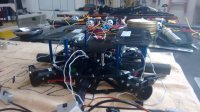
The main objective of this project is to build a dual purpose multirotor, able to fly heavy lift payloads for videography and lightweight cameras for aerial mapping.

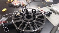
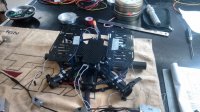
We want to be able to fly different missions, with minimal part changes. To achieve this we decided to maintain the center frame (flight controller, power distribution board, battery packs) and change booms (with motor and ESCs at the end) when wanted. Open the case, get the center frame, choose booms and fly. This first part of the build consists of the heavy lift configuration, and parts for the long endurance config still need further research to be purchased. This build will have an A2 controller (because we have a spare one at the shop), but later will be changed for a Pixhawk, which is our preferred controller for aerial mapping).

Objectives:

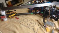
- Small form factor when disassembled for ease of transport
- Quick-release arms
- One carrying case for both multirotor configurations
- Quick release system for different camera gimbals
- Heavy lift payload around 5kg (Red Epic + Light Lenses)
- Light weight payload: Sony A7R

Parts used for HL configuration:

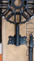
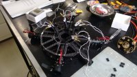
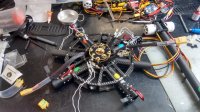
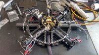
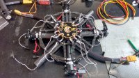
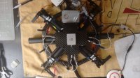
- Cinestar 8 frame X-8 configuration
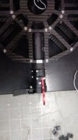
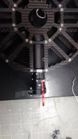
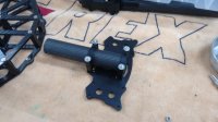
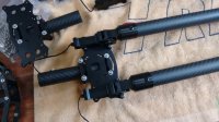
- Famoushobby 25mm metal boom clamps
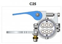
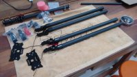
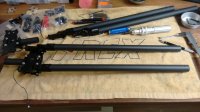
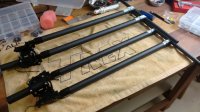
- Catalyst Machineworks 500mm C25 quick release boom system
- Avroto AVL3520/520 motors
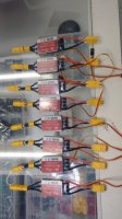
- Spyder 60A Opto ESCs
- Foxtech Supreme 1550 props
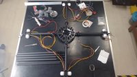
- DJI A2 Controller (later to be changed to Pixhawk)
- Ronin M Gimbal
- Foxtech FPV D130 dual landing gear
- Powerhungry PHS-10 distribution board
- Tattu 10A 6S battery packs

Parts used for Long Endurance configuration:

- Cinestar 8 frame X-4 configuration
- Catalyst Machineworks C25 quick release boom system
- KDE 7208XF-110 or Tmotor U8 100kv (to be decided)
- KDE Direct XF UAS 75A+ or Foxtech Multi-Pal OPTO 80A HV ESC (to be decided)
- KDE Direct 27.5" x 8.9 or Foxtech Supreme 2880 (to be decided)
- Pixhawk Controller
- Custom built Gimbal (for Sony A7R)
- Tattu 10A 12S battery packs
- Powerhungry PHS-10 distribution board

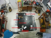
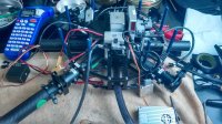
View attachment 26913
 

Attachments

  • benchtop.jpg
    benchtop.jpg
    113.9 KB · Views: 555


Carapau

Tek care, lambs ont road, MRF Moderator
My only thoughts are that where the booms join together, there isnt a very deep join. This is a real weak spot I think, especially if carrying a heavy set up. The potential for movement in the arm and resonance is quite large I would say. When I had a v1 Gryphon Dynamics frame, there was terrible frame resonance on account of the folding arm joints not being solid enough. Funnily enough Gryphon, shortly after my aircraft crashed due to the resonance, released a joint reinforcement upgrade and then changed the join system all together.
 

Carcara

Member
My only thoughts are that where the booms join together, there isnt a very deep join. This is a real weak spot I think, especially if carrying a heavy set up. The potential for movement in the arm and resonance is quite large I would say. When I had a v1 Gryphon Dynamics frame, there was terrible frame resonance on account of the folding arm joints not being solid enough. Funnily enough Gryphon, shortly after my aircraft crashed due to the resonance, released a joint reinforcement upgrade and then changed the join system all together.

Hello Carapau,

I too had some issues with more then one folding/quick-release arm systems at the past. Actually I have been researching for a long time and at the end I decided to try this one. I did some bench test and was impressed with the quality and stiffness of the system. That is the deepest joint I found on the market, and its very tight (at least when its new), and even kind of hard to pull them apart. After joining the 2 parts, you still have a clamp with adjustable tightness (really useful for future play) and a last lock to secure and prevent coming apart. This is definitely well made and thought out. But I think its a good idea to check for possible play on bullet connectors over time and change them if needed.

I performed 2 tests, one for vibration resistance and weight tolerance (they have a similar test on their website but I preferred to make my own test as well). For the vibration test I left the system running for almost half an hour to check possible play on screws and parts. It produced some heavy vibration, a lot more then we would expect on brushless motors, and at the end it was totally intact, with no play at all.

Take a look at the tests I did:

Vibration test:

Load test:
 
Last edited by a moderator:


Carapau

Tek care, lambs ont road, MRF Moderator
Carcara, good tests. Are you sure the flex in the arm is not happening at the joint? Looking at the video you took ie on the tripod mounted camera, it looks like the angle changes at the joint- it could of course be my bad laptop screen?
 

Carcara

Member
Carcara, good tests. Are you sure the flex in the arm is not happening at the joint? Looking at the video you took ie on the tripod mounted camera, it looks like the angle changes at the joint- it could of course be my bad laptop screen?

Carapau,
let me try some more tests with a better set of lens and let's find out. Looking directly to it sure looks like the flex happens at the tubes and mostly at the plastic clamps holding the tube. With better lens and zoom we can try to go deeper on the joints. Let me get back to you.
 
Last edited by a moderator:

Carcara

Member
Carcara, good tests. Are you sure the flex in the arm is not happening at the joint? Looking at the video you took ie on the tripod mounted camera, it looks like the angle changes at the joint- it could of course be my bad laptop screen?

Carapau,
I made more tests, sorry the video ended up a little bit too long, but you can see more details about the mechanism. Note that at the end of the video I mention some movement, which will be eliminated once the boom is set up flush with the central plate's metal boom clamps. The plastic boom clamps I used for the test IMO are the weakest point that show any kind of flex. I might sound a bit boring or repetitive, but as I mentioned on an earlier post, I had problems before with other quick release solutions and I want to assure the next one will solve the problem (the possibility of taking the copter apart on a small factor is something worth the time on research IMO).
Let me hear your thoughts.

Joint test:
 

Carapau

Tek care, lambs ont road, MRF Moderator
That's great testing and for something like this project a wise thing to be doing! I am a bit suspicious of folding mechanisms as they can be real weaknesses in a frame although done well then of course they are excellent. I have seen a few people on here rush into building their rigs and believing that it will work only to see the aircraft plow into the ground (it has also happened to me). This is always painful to here about. So I dont intend to be negative about this but just want to see you be successful with it. The clamp looks solid enough although I am still suspicious of the depth of the join of the clamp- it seems to only be about a cm or 2 but your testing is doing a good job of determining if that is indeed a weakness or not.
 

Carcara

Member

Attachments

  • IMG_20151125_104119152.jpg
    IMG_20151125_104119152.jpg
    101.9 KB · Views: 305
  • IMG_20151125_104156925.jpg
    IMG_20151125_104156925.jpg
    80.5 KB · Views: 478
  • IMG_20151125_104221824.jpg
    IMG_20151125_104221824.jpg
    112.6 KB · Views: 443
  • IMG_20151125_104625028.jpg
    IMG_20151125_104625028.jpg
    104.2 KB · Views: 461
  • IMG_20151125_104720337.jpg
    IMG_20151125_104720337.jpg
    111.1 KB · Views: 297
  • IMG_20151125_105125903.jpg
    IMG_20151125_105125903.jpg
    99.8 KB · Views: 303
  • IMG_20151125_104646601.jpg
    IMG_20151125_104646601.jpg
    107.6 KB · Views: 291

Carcara

Member
I sent an e-mail to the manufacturer of the C25 quick release system, asking about the optimum position for installing the booms at center frame. Below is his response. I thought it would be interesting to share for whom may be following the build. I sent him the following 2 pictures, and after that you can read his replies.

View attachment 26961 View attachment 26962

Response:
"The C25 is designed to be mounted up flush to the center hub of the craft (like picture 2). This keeps overall size of the detached hub smaller for travel.

Plus I noticed in your pull tests you had the couple rotated 90 degree from where its optimum orientation is. You want to mount it and pull it at 90 degree to where you had it. In other words the red clamp should not be facing straight up but rather parallel with your work bench. This will most likely stop that little bit of movement you saw where the interior coupling edge mates to the CF tube."

After that I asked about the optimum pressure one would apply to the main tube clamps...

Response:
"This is a little of a gray area to be honest. The reason is every carbon fiber tube manufacturer produces tubes with slightly different OD's. And the same manufacturer will produce two batches with two different OD's! The C25 will compress down to that OD. So the required position of the arm might be different from tube to tube.

BUT, as a general rule set the arm as in the picture. Or maybe even with the top of the arm horizontal for a nice tight fit. You can get a feel for what is correct after a while. Also, with the testing you did it will help you to know where that "sweet spot" is."

View attachment 26963

What a great customer support, that's all I can say. You should take a look at their instructions manual, amazing quality. Let's hope it works as expected.
 

Attachments

  • IMG_20151201_173029330.jpg
    IMG_20151201_173029330.jpg
    32.2 KB · Views: 306
  • IMG_20151201_173042888.jpg
    IMG_20151201_173042888.jpg
    37.1 KB · Views: 321
  • Arm.jpg
    Arm.jpg
    28.3 KB · Views: 328

Motopreserve

Drone Enthusiast
That's some nice CS. Glad to see they were able to point you in the right direction (pun intended) and you should now be good to go.

Keep the updates coming!


Carcara

Member

Attachments

  • IMG_20151127_181438606.jpg
    IMG_20151127_181438606.jpg
    97.7 KB · Views: 489
  • IMG_20151127_181555858.jpg
    IMG_20151127_181555858.jpg
    46.8 KB · Views: 447
  • IMG_20151201_100328928.jpg
    IMG_20151201_100328928.jpg
    114.9 KB · Views: 627
  • IMG_20151201_100542255.jpg
    IMG_20151201_100542255.jpg
    48.8 KB · Views: 293
  • IMG_20151201_112947173.jpg
    IMG_20151201_112947173.jpg
    98.9 KB · Views: 335
  • IMG_20151201_141355401.jpg
    IMG_20151201_141355401.jpg
    128.1 KB · Views: 473
  • IMG_20151201_141403264.jpg
    IMG_20151201_141403264.jpg
    131 KB · Views: 464
  • IMG_20151201_145738079.jpg
    IMG_20151201_145738079.jpg
    132.2 KB · Views: 434


Holly cow! That thing is looking nice! Curious what is the distance (in mm) from the motor shaft to the main clamp on the C25?
 

Carcara

Member

Attachments

  • IMG_20151202_101034615.jpg
    IMG_20151202_101034615.jpg
    127.8 KB · Views: 417
  • IMG_20151202_105742083.jpg
    IMG_20151202_105742083.jpg
    136 KB · Views: 257
  • IMG_20151202_120619680_HDR.jpg
    IMG_20151202_120619680_HDR.jpg
    158.2 KB · Views: 293
  • IMG_20151202_130337872_HDR.jpg
    IMG_20151202_130337872_HDR.jpg
    144.4 KB · Views: 308
  • IMG_20151202_211336382_HDR.jpg
    IMG_20151202_211336382_HDR.jpg
    149.5 KB · Views: 704
  • IMG_20151207_183126196.jpg
    IMG_20151207_183126196.jpg
    118.7 KB · Views: 680
  • IMG_20151207_183130334.jpg
    IMG_20151207_183130334.jpg
    140.4 KB · Views: 316
  • IMG_20151207_193112426.jpg
    IMG_20151207_193112426.jpg
    132.1 KB · Views: 283


Vitaly

Member
Hi,
i think it's good engeneering experience, but in practice - there is no much utility. As you can see, no one uav-manifactuaring company in the world produce such dual-purpose drone. I think, there is two reasons for it:
1. Main reason: i don't think can be real necessity promptly take off RED, transform X8 to quadrocopter and quiqly start aerial mapping. Frankly speaking, i can't imagine such situation. Mayby i'm wrong?
2. Technical issue. I think, nowdays copter hardware is not so flexible to allow speedy transform from X8 heavyliter to light quad.
Anyway - good luck! And "stay hungry!"(c.)
 

Carapau

Tek care, lambs ont road, MRF Moderator
1. Main reason: i don't think can be real necessity promptly take off RED, transform X8 to quadrocopter and quiqly start aerial mapping. Frankly speaking, i can't imagine such situation. Mayby i'm wrong?

I do this all the time. One minute flying an Alexa Mini and the next doing some agricultural mapping. I use the same machine for both which is a bit overkill for the mapping- but it does the job perfectly.
 

Top