The "X-I" shaped frame - Something a little different

thothtp

Member
So I am new to multirotors, but have been browsing the forums and reading everything I can for a while now. I have decided that I want to jump in to building one, and I want one stout enough that I can haul a go-pro camera now, and possibly upgrade to full FPV later. I was originally going to go with a bought frame, but being an industrial designer and mechanical engineer by career, with a full prototype shop at work, I decided that designing and building my own would be more fun/rewarding, and tailor it exactly to my needs.


I started thinking about the basic H or X frames, but the H frames worried me with their tendency to twist flex and transmit vibrations, and the X frames had the problem of the props being visible in the video.


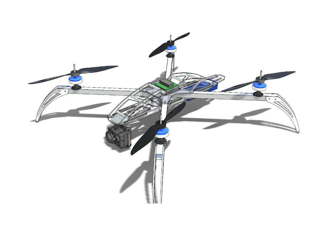
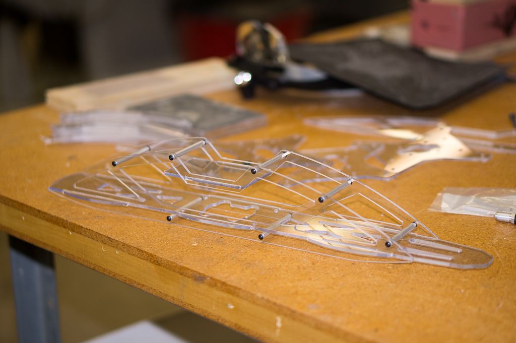
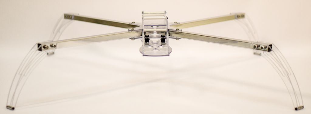
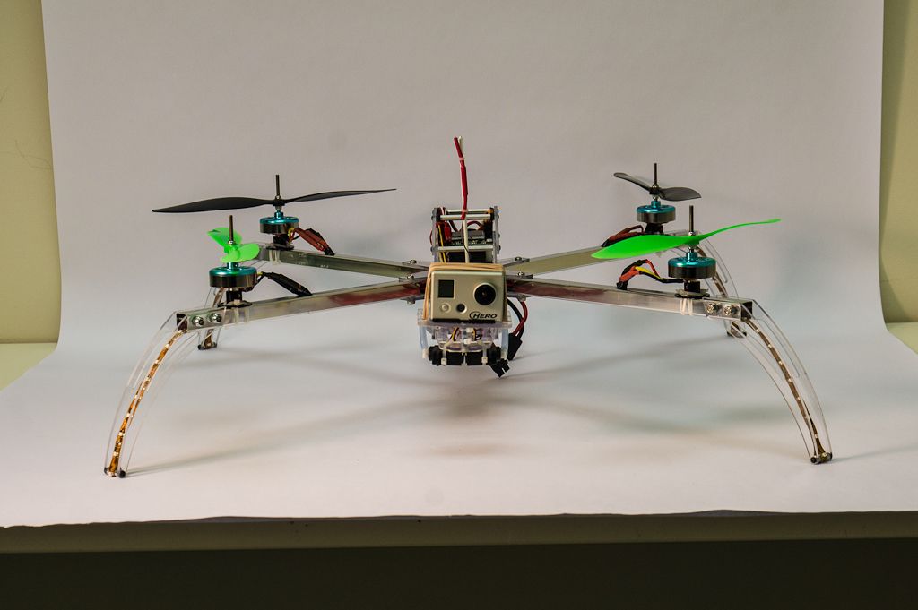
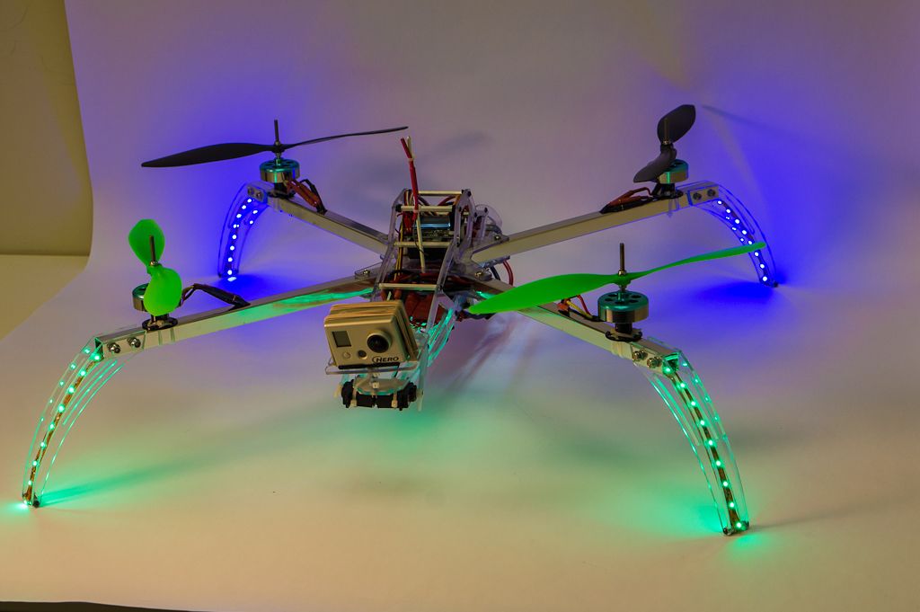
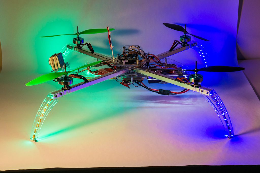
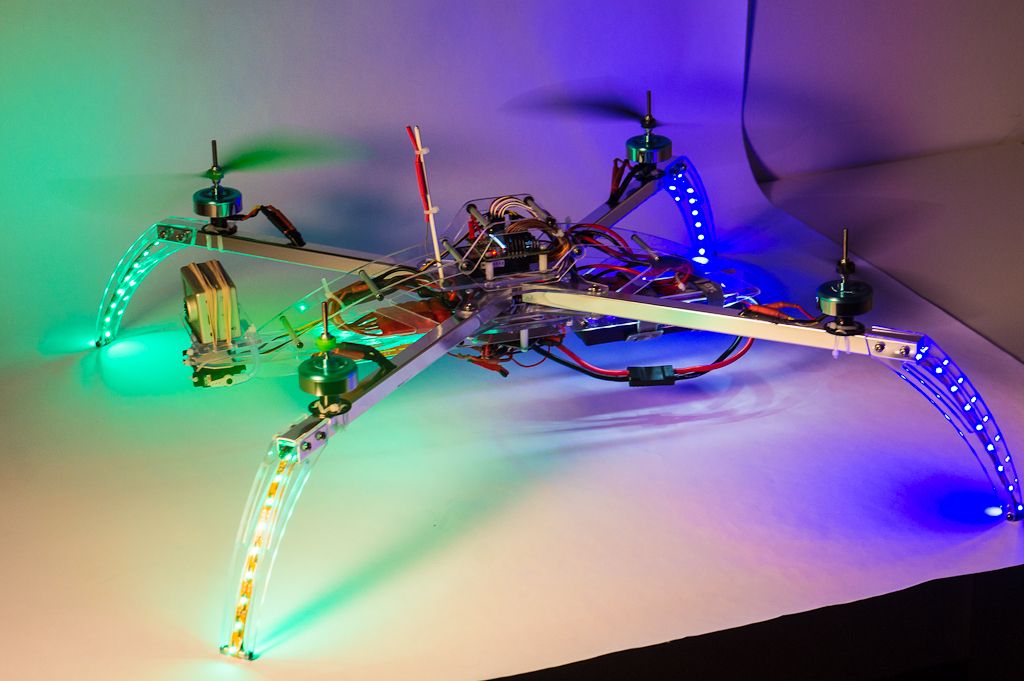
So I had the idea to combine a simple X frame with a separate lightweight center frame (the I in the X-I name) to move the camera forward and the battery backwards, and to have that whole frame be heavily isolated from the motor booms for vibration resistance.


Theoretically, by mounting everything heavy and sensitive to a single frame structure, and then isolating that from the main motor/boom structure, it should provide extra vibration damping, while still being light weight and stiff.


That's the theory at least, so here are the pictures.


X-Iconcepttp1_zps67e5ef2c.jpg


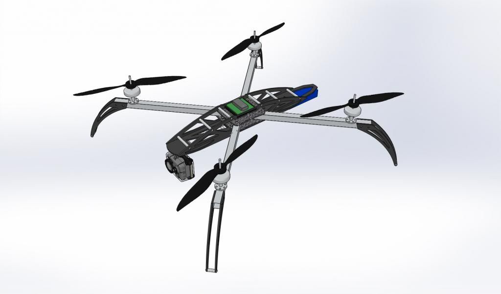
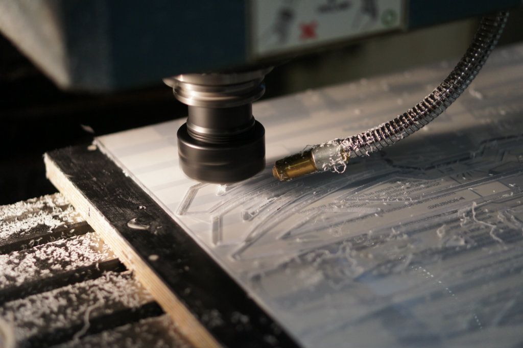
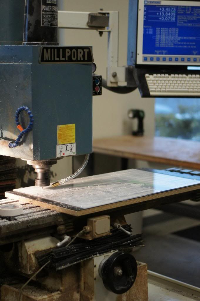
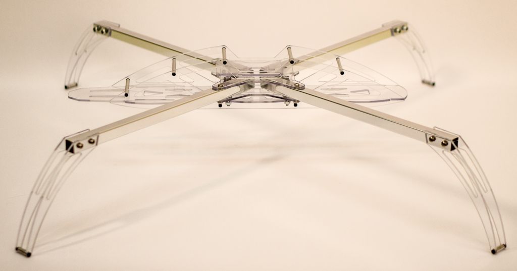
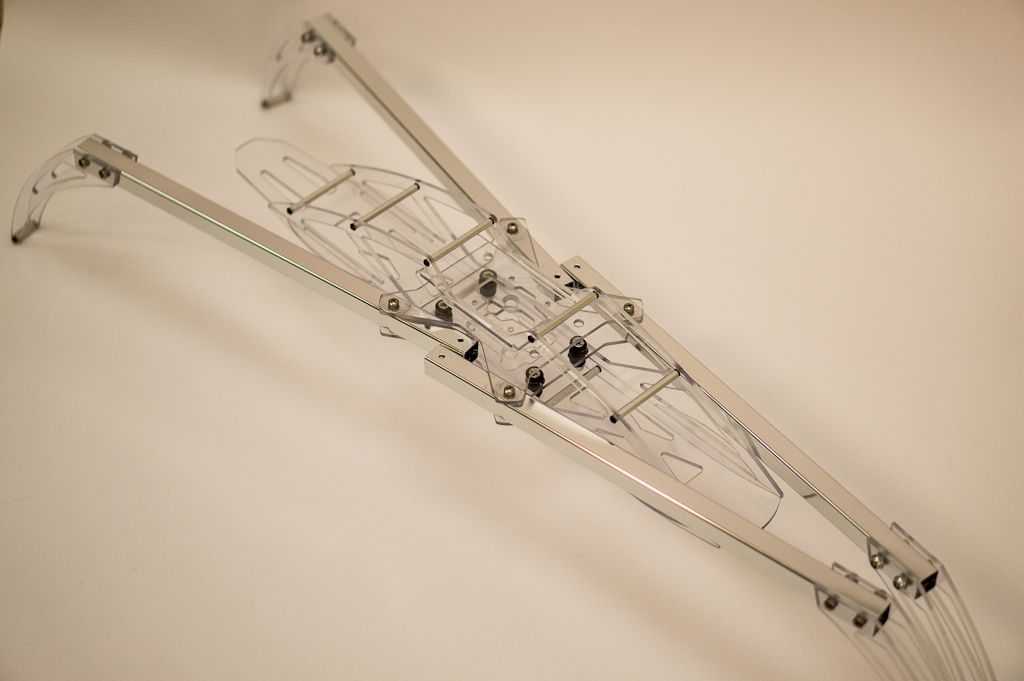
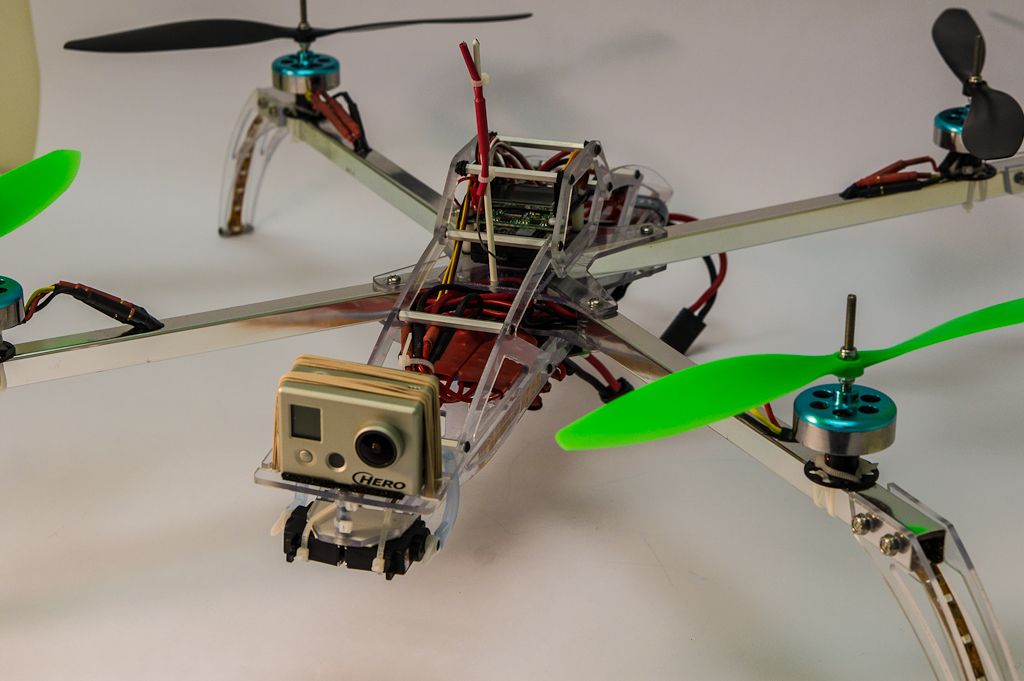
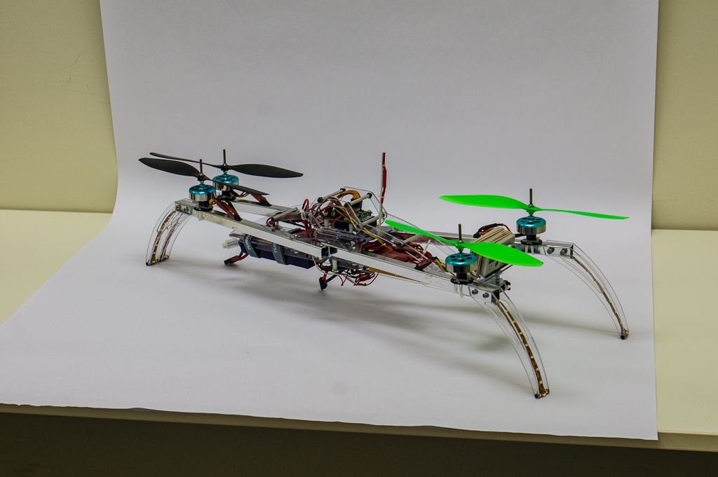
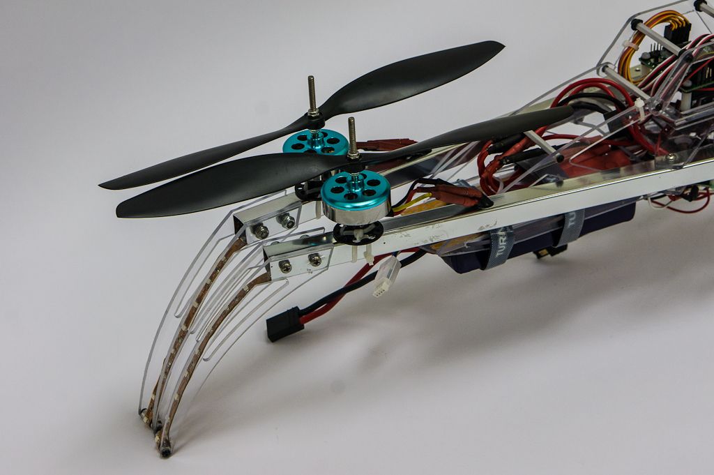
The main boom arms are home depot towel bars, while the plates making up the rest of the frame are 1/8in polycarbonate sheet, to be upgraded later to G-10 or CF. The rest of the hardware are off the shelf standoffs screws and washers from Mc-Master Carr (or the supply room at work)


X-Iconcepttp2_zps50c2bffe.jpg


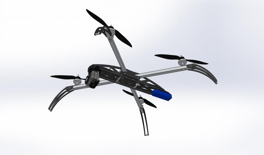
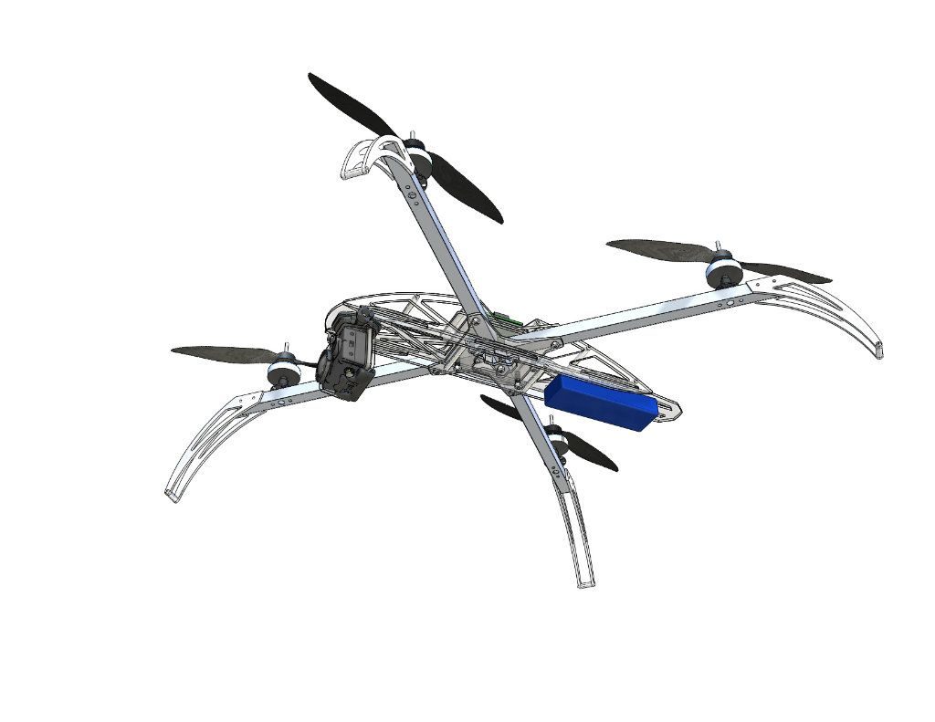
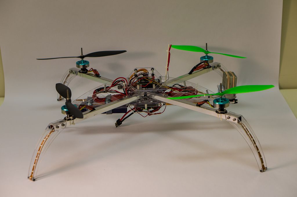
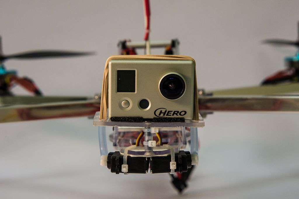
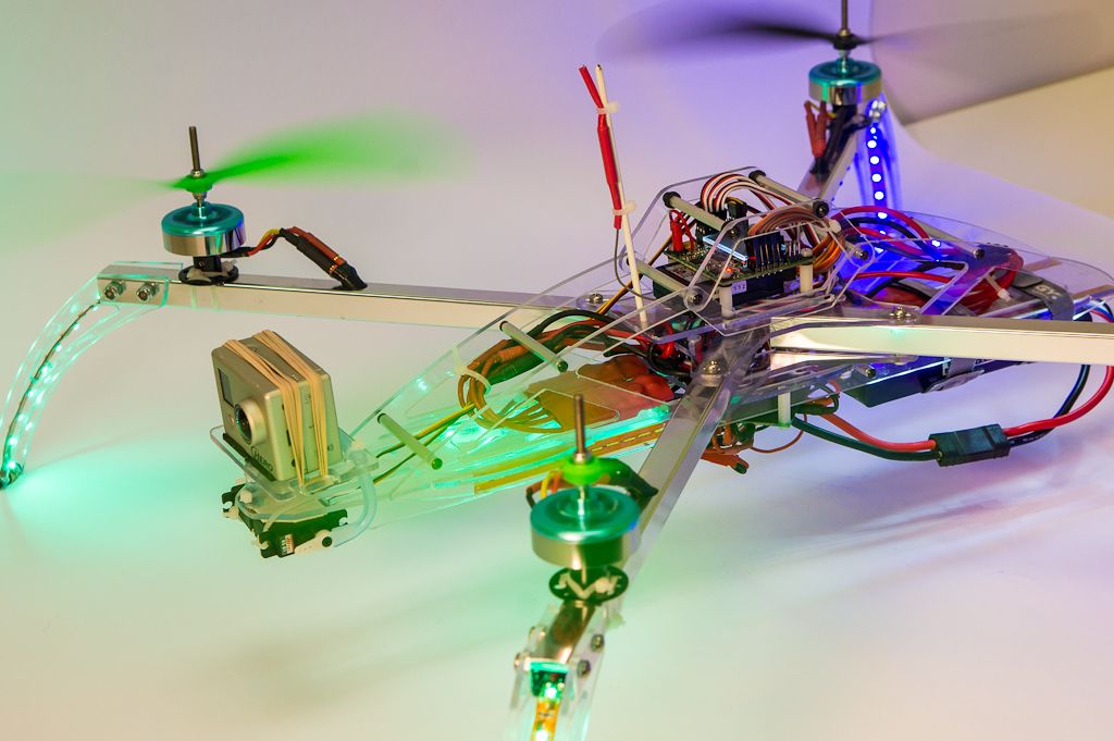
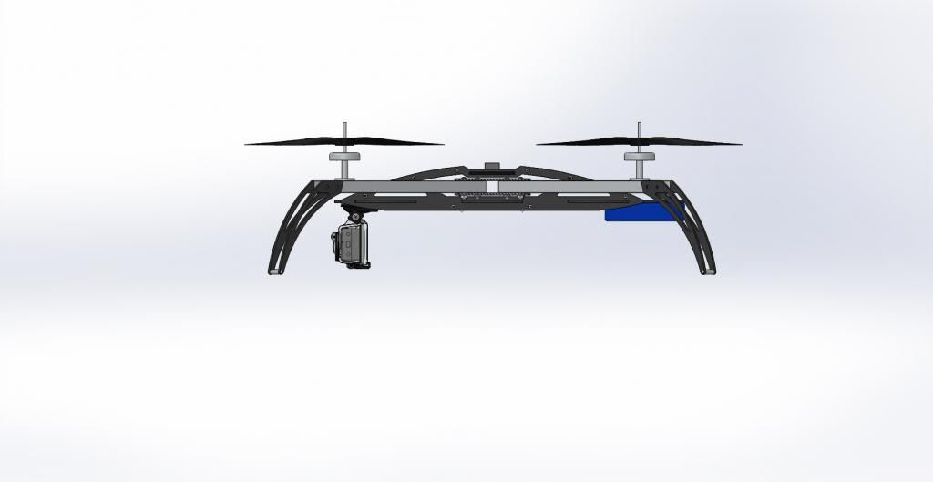
The go-pro and battery are hung below the main frame, keeping the weight on the dampened section to help absorb any vibration that makes it through the rubber washers.


X-Iconcepttp3_zps6770d7c4.jpg


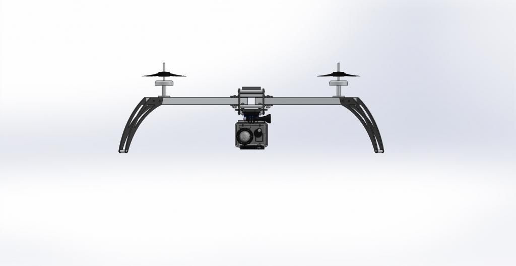
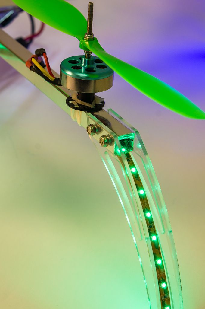
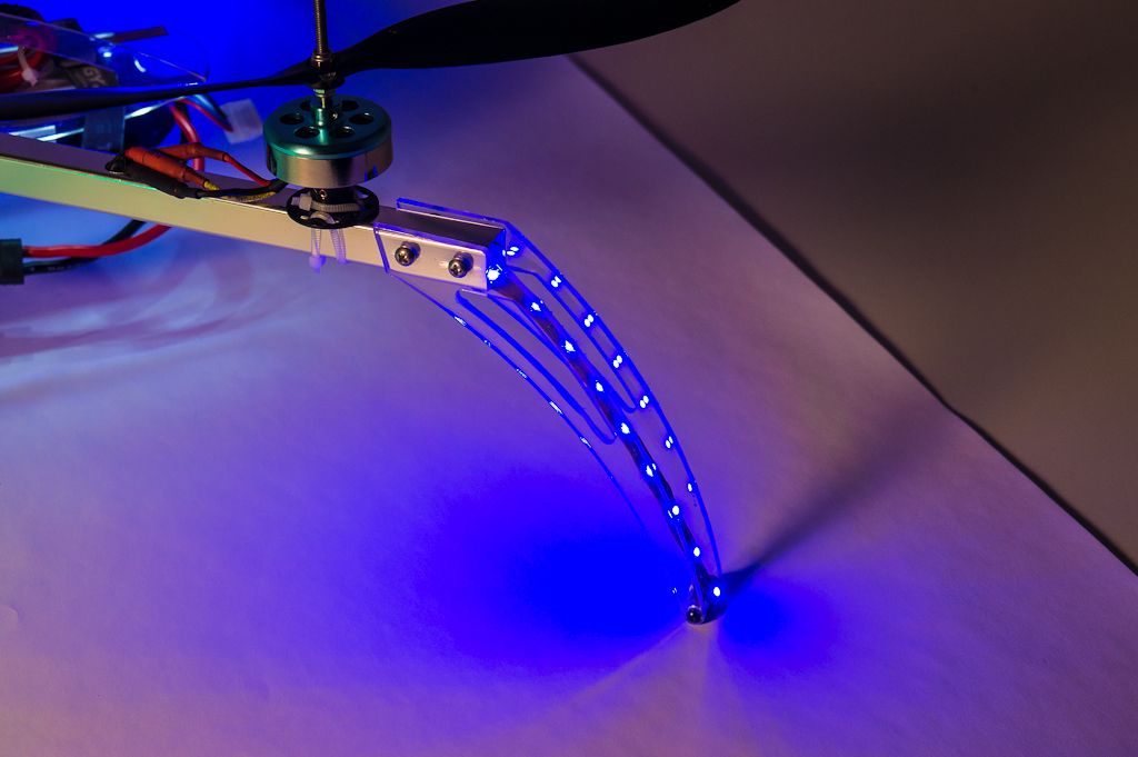
The feet are splayed outward to help protect the props in a crash


X-Iconcepttp4_zpsceee234e.jpg


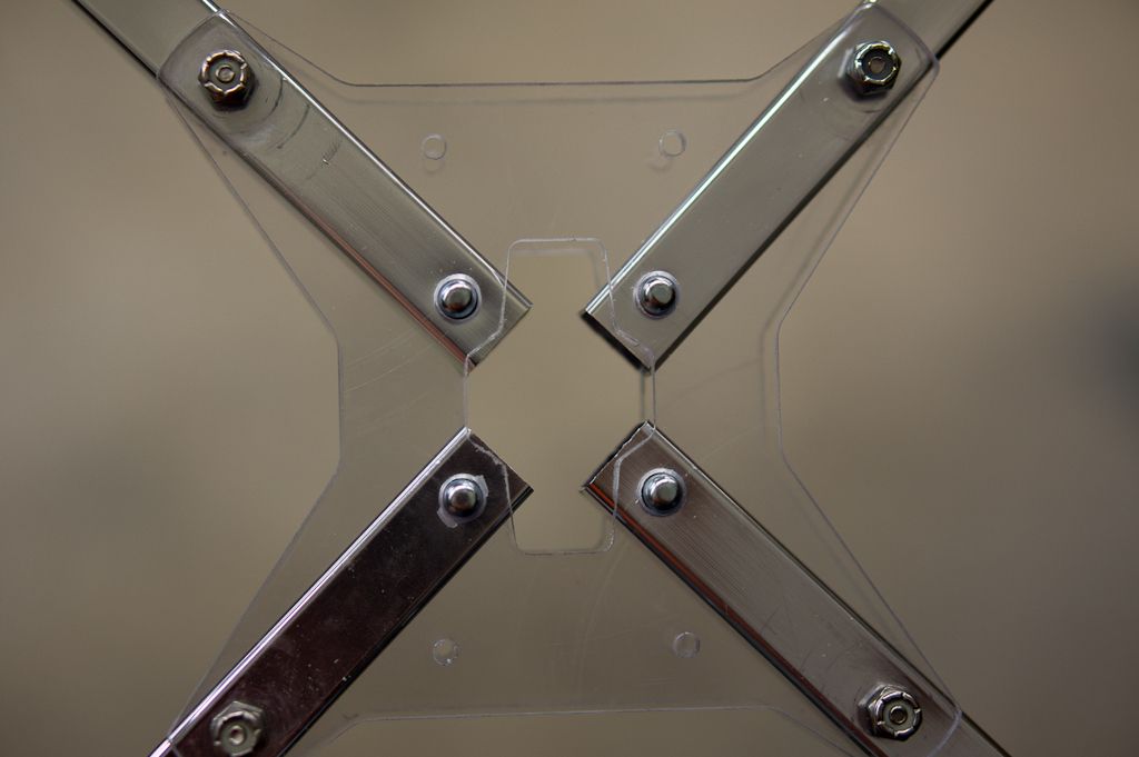
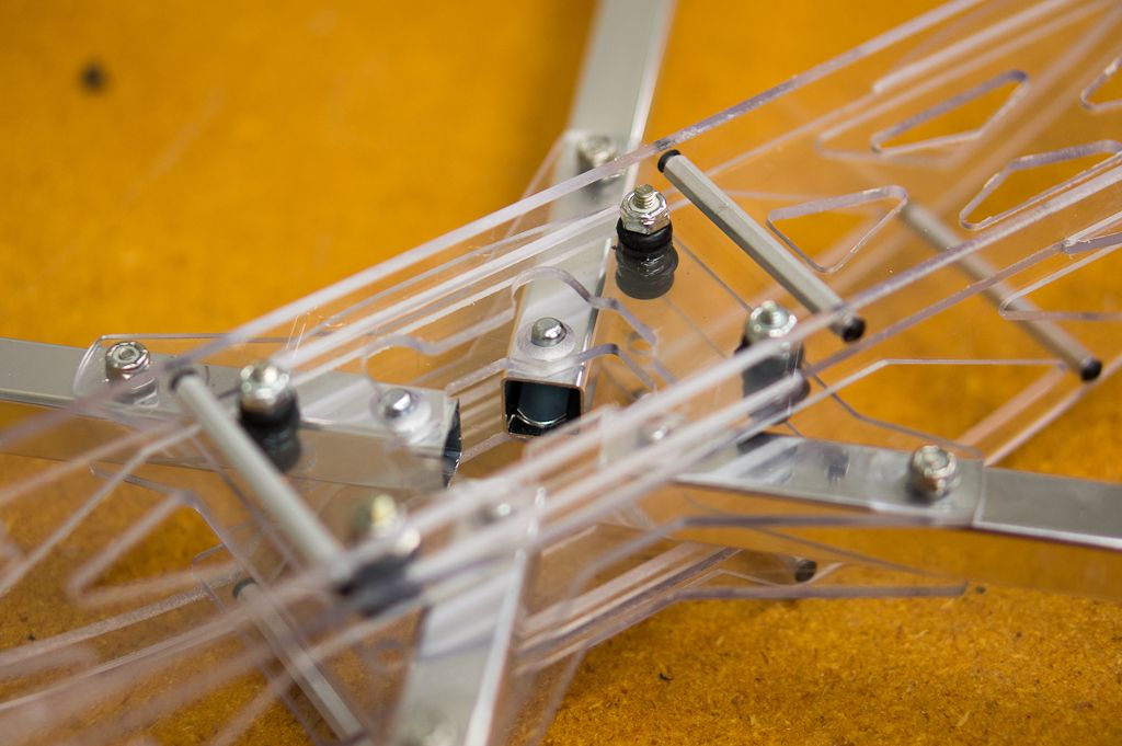
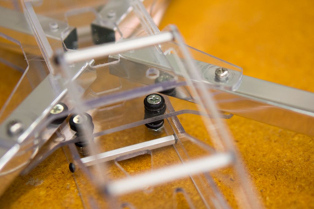
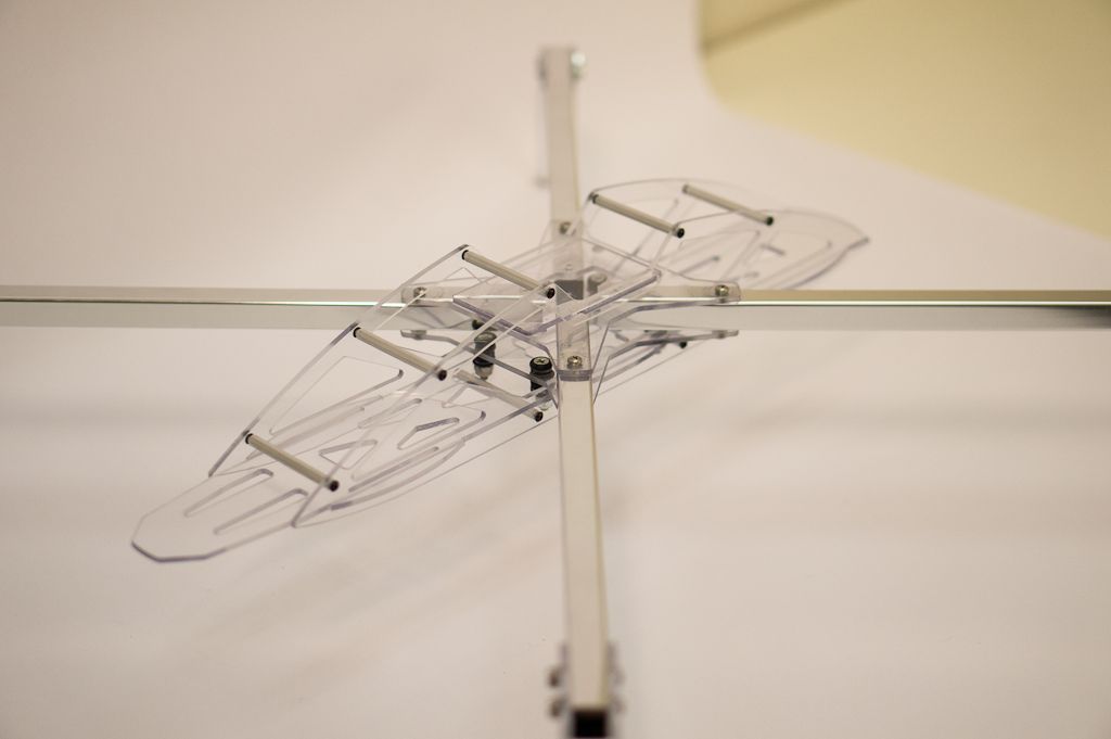
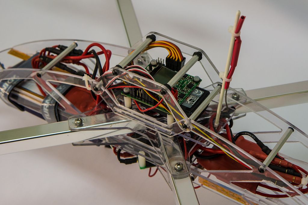
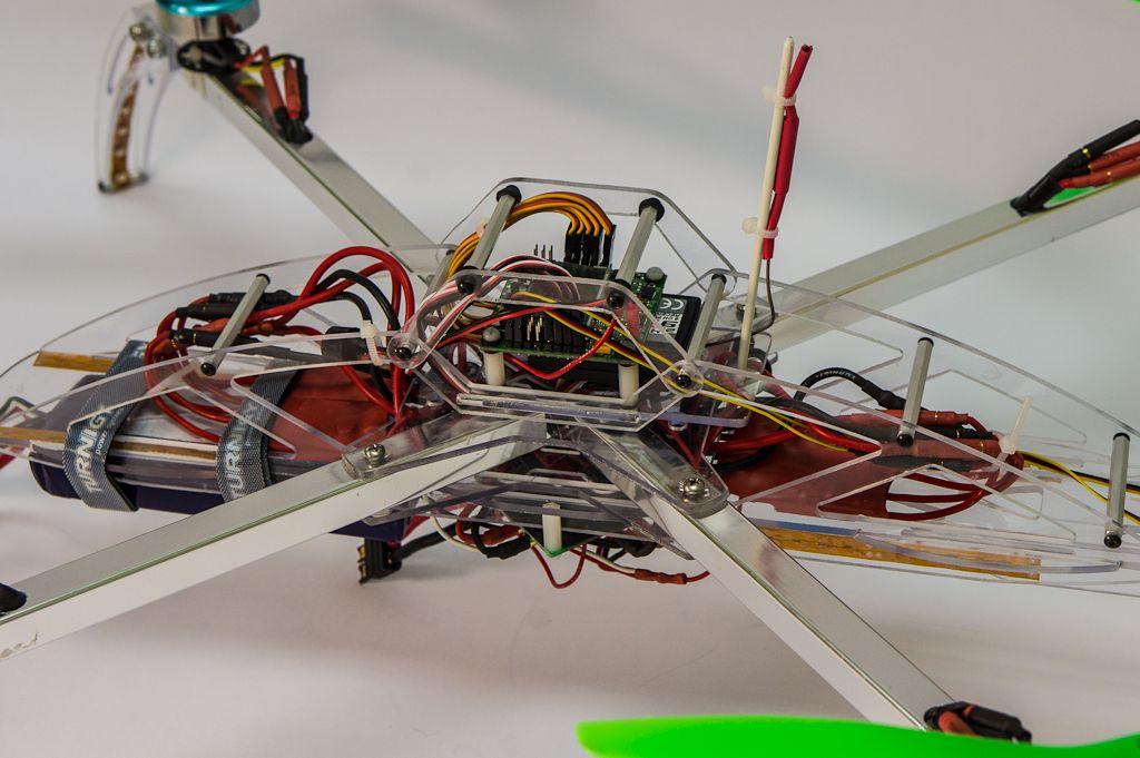
The main "I" frame is connected to the X frame solely just below the center of the X, while the rest of the frame does not contact.


X-Iconcepttp5_zpseefca1a5.jpg


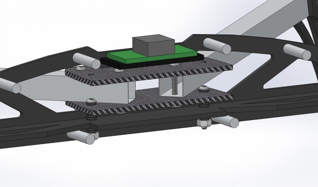
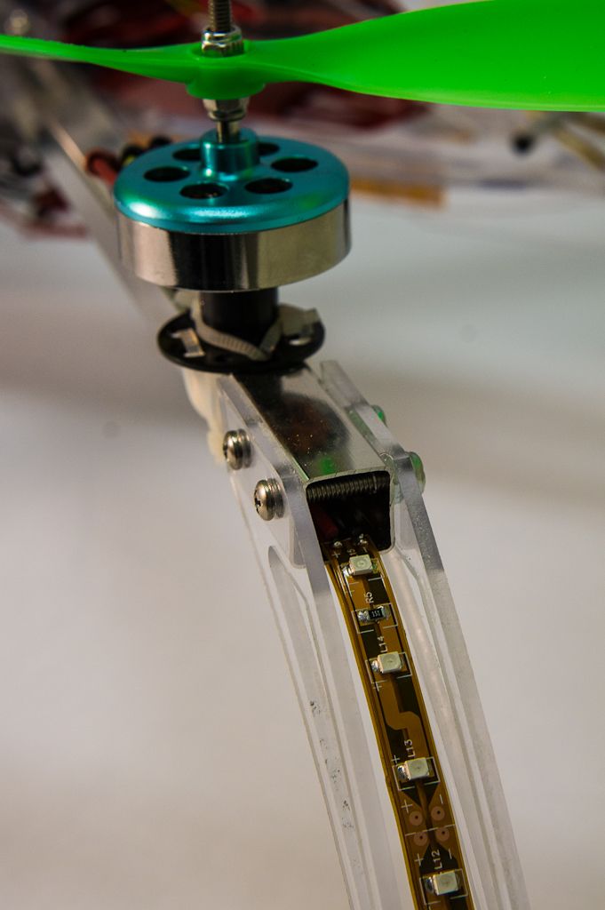
In this cross section you can see how the X frame plates are attached to the I frame with a set of rubber washer shock absorbers. The amount of rubber will have to be tuned to give good rigidity while absorbing vibrations.


The motor to motor diagonal is 550mm, and according to my solidworks calculations, the frame should be around the 400g mark, with an AUW of around 1500g. Coming from the RC car world, and being a designer, I am also planning on designing and vacuum forming a lightweight lexan body shell, to protect the electronics, improve aerodynamics, and most of all, because it will look cool. That will come once I finalize the frame design. Should add very little weight, it will be very thin.


So that is my work in progress design. Currently all the cut pieces fit on a single 1'x2' sheet, so costs should be low.


The components I am planning to use so far are these:


Hextronic DT750s
http://www.hobbyking.com/hobbyking/store/uh_viewItem.asp?idproduct=6247


Turnigy Plush 25 amps (30s are out of stock)
http://www.hobbyking.com/hobbyking/store/uh_viewItem.asp?idproduct=2163


Hobbyking KK2.0 LCD board
http://www.hobbyking.com/hobbyking/store/uh_viewItem.asp?idproduct=24723


Slow fly 11x4.7 props (just linking one here, know I need 4 different ones)
http://www.hobbyking.com/hobbyking/store/uh_viewItem.asp?idproduct=22452


Various wires and connectors, USB programmer, Turnigy 9x, ect.


So, this is meant to be a combination build thread and discussion/critique, so I ask you, does this look like a good plan? Are my component choices ideal for what I am trying to do here? Is that combination of motor/prop going to work for me? What am I missing? Am I crazy and should go with something typical?


Like I said, I am new to this, so I need all the advice you guys can give me, thanks for the help!


brind0g

Member
Funny I was just talking last night about using an old plane body and having 4 booms coming off it in a X formation.

You design looks very good, and If I were you, would look at mass producing them, im sure they would be a hit as it sounds like u know ur stuff and have come up with a pretty damn good design!!

The idea with the legs helping protect the props, love it!! I snapped 10 props before I even left the ground!! :D

Cannot wait to see the end result!!
 

There's a reason you see other landing gear with the points toward center, opposite from your chosen direction. If you land moving forward you want the front landing gear to skid and the rear gear to catch. The way you have it your front gear are going to catch and flip you on landing if you are landing in any moving direction besides hover, which is quite common.

Why use towel bars when it's very easy and nearly as economical to find graded tubing on the internet? That way you know what alloy and what strength. With towel bars you are going to be guessing and that usually means heavy. Also round tubing has more torsional rigidity than square although it's harder to design and build when trying to attach items to a round shape. There's a reason all the pro craft that use tubing have round tube.

With the combination of the H and the X I'm guessing that for the same torsional rigidity you are going to be heavier. The center of the typical H craft accommodates some of the distance from craft center to motor center, thus it's arms are shorter and lighter. You have this center H weight and then the longer arms of the X design.

One of the things you have right is the majority of the weight in the vibration isolated area. I'm designing an H multi-rotor right now and need to work this more into the design.

I like the curved top design and the body idea also.

Please critique my build if you get a chance. It's here on fpvlab

http://fpvlab.com/forums/showthread.php?10655-Custom-Build-Quad

thanks
 

thothtp

Member
There's a reason you see other landing gear with the points toward center, opposite from your chosen direction. If you land moving forward you want the front landing gear to skid and the rear gear to catch. The way you have it your front gear are going to catch and flip you on landing if you are landing in any moving direction besides hover, which is quite common.

Why use towel bars when it's very easy and nearly as economical to find graded tubing on the internet? That way you know what alloy and what strength. With towel bars you are going to be guessing and that usually means heavy. Also round tubing has more torsional rigidity than square although it's harder to design and build when trying to attach items to a round shape. There's a reason all the pro craft that use tubing have round tube.

With the combination of the H and the X I'm guessing that for the same torsional rigidity you are going to be heavier. The center of the typical H craft accommodates some of the distance from craft center to motor center, thus it's arms are shorter and lighter. You have this center H weight and then the longer arms of the X design.

One of the things you have right is the majority of the weight in the vibration isolated area. I'm designing an H multi-rotor right now and need to work this more into the design.

I like the curved top design and the body idea also.

Please critique my build if you get a chance. It's here on fpvlab

http://fpvlab.com/forums/showthread.php?10655-Custom-Build-Quad

thanks


That is a good point on the landing gear, I am hoping that the extra wide stance will help mitigate the chance of flipping. I wanted them to serve as prop guards as well, without adding extra weight. If flipping becomes a problem, I may redesign the feet to act more like skis in the direction needed. Good Advice.

I am aware that round tubing is stronger, but I went with square for the ease of assembly and the weight savings of not needing mounting blocks. We will see how it works out, but a later model made of more expensive materials will probably incorporate round tubing. I went with the Towel bar specifically because it was light, much lighter then the tubing that I was able to find locally, and being able to replace parts with local sources was important to me. I'll see how it works out, may end up switching it.

It will definitely end up heavier then an X, but I think for a given torsional rigidity it should end up the same or lighter then an H, because an X is so much easier to make rigid corner to corner. The I part of the frame is designed extremely lightly, with the arch giving it lots of strength with very little material. We will see, its all part of the experiment!

Thanks for the advice!


I have finalized the CAD design, and we have started cutting the prototype. Here are some pics of the final design:


UAVConceptf1_zps5efa7140-1_zps84beef47.jpg

UAVConceptf2_zpscbf350a3-1_zpsa305c18f.jpg


I have ordered all the parts, and have begun cutting parts on the CNC mill here at work.


DSC07859_zpscc785ef6-1_zpsb84595bb.jpg

DSC07861_zps4345d6a3-1_zps706979c6.jpg


I'll keep this updated as I go!
 

thothtp

Member
Parts are together and the frame is built! Hit my weight target, and it came out even better then I expected.


Here is the main frame put together for the first time
print-1_zpsb1672025.jpg


Here I am showing the hand release folding mechanism. It uses spring pins similar to an umbrella or EZ-UP, which lock the frame arms in place but allow you to fold it up in seconds without tools. I was worried about rigidity here, but it looks to be rock solid.
print-2_zpscac55484.jpg


Looking at the bottom with the arm frame in place, you can see the vibration isolating grommets.
print-3_zps4ec12458.jpg


The X frame with the motor mounts is entirely isolated from the main frame housing the electronics. These grommets completely surround the hard parts so that there are no plastic or metal parts touching, only rubber.
print-4_zps76ade0dc.jpg


Forgive the mess here, this is our silicone soft tooling mold room, only place I could find an accurate scale. The full frame with all hardware comes out to 1.15 pounds, or 521 grams. Keep in mind this is using quite heavy (but very very cheap) 3mm (1/8in) polycarbonate sheet and aluminum arms - If made with carbon or G-10 that weight would drop a ton. I was trying to keep it under 600g, and with all the features it has I am very happy with the result.
print-5_zps0032c411.jpg


And finally some pictures of the complete frame
print-7_zpsa5cf01d5.jpg


print-8_zps6f645c99.jpg


print-9_zpsea30ad26.jpg


print-10_zps8c3b9db6.jpg


and finally, a video!


I'll keep this updated as I get started on the electronics, still waiting on the order to make it across on the slow boat from China :-(
 
Last edited by a moderator:

Coming together nicely. What CAD and what CAM program did you use?

So you have a vacuum forming setup for Lexan in your shop? I'm jelly ;>)
 

thothtp

Member
Coming together nicely. What CAD and what CAM program did you use?

So you have a vacuum forming setup for Lexan in your shop? I'm jelly ;>)


I use Solidworks for design work. We use Rhino CAM for machining.

We do have a small vacuum former, so I can machine a pattern and form a body without too much trouble. Just want to get the mechanics down solid before I invest in a pattern (the renboard material we use for tooling is pretty pricey)
 

So what file type did you export from SW to use in Rhino CAM? Did you run Rhino as 2d or 3d?

How did the "mass properties" weight of the model in SW compare to the actual weight?
 

thothtp

Member
So what file type did you export from SW to use in Rhino CAM? Did you run Rhino as 2d or 3d?

How did the "mass properties" weight of the model in SW compare to the actual weight?


We usually export both a step and an Iges, and see which one comes in cleaner. I think this time it was Iges. All 3d. Then in Rhino we just extract the outlines and do a profile machining. The mass properties weight in solidworks was actually spot on, within about 5 grams, which was really surprising.
 

thothtp

Member
Its alive! Got everything wired up and functioning, and it has flown! Still working on getting all the tuning done, and still need to balance the props, but it is working great so far. The frame has plenty of room for everything, is very stiff and rigid, the folding works great, and even with out of balance props the vibrations are sucked right out of it. Very happy so far!


I ended up adding crezzee's Super Simple Gimbal (http://www.rcgroups.com/forums/showthread.php?t=1793759) to auto balance the go pro, and it works great! Here is a video!


http://youtu.be/STPiBHNHlWk


Once I get it tuned and balanced (and learn to fly it, heh) I will update this with some on board flight videos. Here are the photos


print-1-2_zpsb9733bd0.jpg

print-2-2_zps7ed5d474.jpg

print-3-2_zps032cd13f.jpg

print-5-2_zps3be78c08.jpg

print-6-2_zpsa85146cb.jpg

print-7-2_zps8adfa61b.jpg

print-8-2_zps96ee2bca.jpg

print-9-2_zpsd98e8f56.jpg

print-10-2_zpsa22b5d33.jpg

print-11_zps237dbbed.jpg

print-12_zps6057a707.jpg

print-13_zps792dc09e.jpg

print-14_zps87fe3314.jpg


Here it is folded up, no tools, just click and lock.


print-15_zps2c0ad2e2.jpg

print-16_zps49a81fc1.jpg


I'm already starting to look at FPV, have room for a flight camera below the go-pro, with a transmitter on the back. I do a lot of design and engineering work for Vuzix corporation, and showed the owner what I had built, he wants to give me some goggles to experiment with.


Trying to figure out a decent inexpensive setup to get started with. Not looking for super long range, just something I can use to fly around within 500m or so. Its a big quad copter, I don't see myself going very far with it anyways. I was thinking about picking up a 200mw setup from hobbyking in either 900mhz or 5.8ghz, would that work for me or are they just too crappy? My radio is a Turnigy 9x that I am very happy with so far, but do I need to upgrade to a FrSky module? If the HK one doesn't work, are there any better options within the same price ballpark?


Thanks again everyone!


thothtp

Member
Took it up with the camera today, and was reasonably successful. I haven't done any prop balancing yet, so the video is pretty shaky, and I think the gimbal may be a little too soft, but it flys great! I have almost no experience with flying anything really, so I am trying to learn the ropes and getting bolder each time I take it up.


I also decided to crash test the frame by hitting a tree... on purpose of course! I didn't lose depth perception and accidentally back in to the tree that I thought I was still clear of...


It passed the test with flying colors, after a 30 foot fall it broke a couple props and the frame collapsed like it was supposed to, no damage.


Hopefully I can work out the jello and learn some skills and then I will be good to go!


Here are some images as well, shows my front yard after the big east coast snowstorm.


upload-6.jpg

upload-5.jpg

upload-4.jpg

upload-3.jpg

upload-2.jpg

upload-1.jpg
 
Last edited by a moderator:

VINHEX

Member
Some excellent images well done.. Are these shots from the GoPro? Did you edit them at all.. This is a really cool bird well done...


thothtp

Member
Some excellent images well done.. Are these shots from the GoPro? Did you edit them at all.. This is a really cool bird well done...


Those photos are from the go pro, just set it to take one every couple seconds. Might need to upgrade to a GoPro 3 black edition, they can take photos at the same time as video, would be awesome for this!

Only editing was a little color and noise reduction tweaking in lightroom.


Kilby

Active Member
Nice job. I'm curious how it was working with the Lexan. Did you have an troubles cutting it? I have a few designs that I want to prototype in lexan before cutting the final product in carbon fiber. Any tips for working with that material?

Great job on the quad, btw. Awesome photos of the snow, too!

-Terry
 

brind0g

Member
So when are you going to make these available for the public to purchase? Keen to get my hands on one ;) Great work! very impressive!


Top