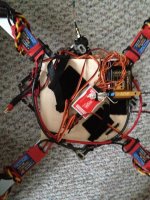
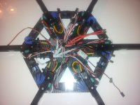
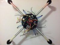
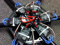
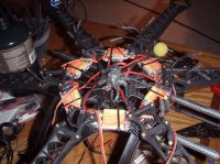
I am getting ready to install the Turnigy Plush 30 escs on my XA Hexa, and am thinking there might be a better way out there to distribute power then how I've done it in the past few multis.
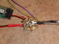
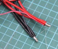
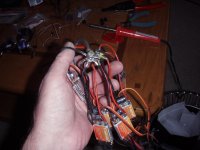
Typically I would solder together 7-8 JST female connectors to an inch or two of 12 gauge wire with a battery connector on the end and then heat shrink everything up nice and pretty.
Although I haven't picked up my Plush 30 escs yet from the post office, I think the wire may be a bit too large for a JST connector. What is the preferred method for connecting the ESC's? Just straight solder them in? I guess that makes sense, but is it the right move?
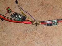
I also need to wire into the mess a jst connector for my telemetry, a second jst for my leds, and I'd like a third spare just in case... A lot of wires!
Typically I would solder together 7-8 JST female connectors to an inch or two of 12 gauge wire with a battery connector on the end and then heat shrink everything up nice and pretty.
Although I haven't picked up my Plush 30 escs yet from the post office, I think the wire may be a bit too large for a JST connector. What is the preferred method for connecting the ESC's? Just straight solder them in? I guess that makes sense, but is it the right move?
I also need to wire into the mess a jst connector for my telemetry, a second jst for my leds, and I'd like a third spare just in case... A lot of wires!


")